Position Meaning
14 and 15 Optical properties 25 = scanning range 2.5 m and mini‐
mum objec
t length 4 mm
00 = special properties
16 and 17 Preconfiguration of the I/O con‐
nect
ions and software
01 = standard
3.2.1 Measurement field width
The MLG-2 consists of measurement modules and optionally empty modules. The mea‐
sur
ement module
s can be located on the connection side and on the head of the
MLG-2. Empty modules do not have LEDs.
rs
M
1
L
2
G
3
0
4
5
5
W
6
–
7
0
8
2
9
1
10
3
11
x
12
x
13
x
14
x
15
x
16
x
17
3
1
2
1
32
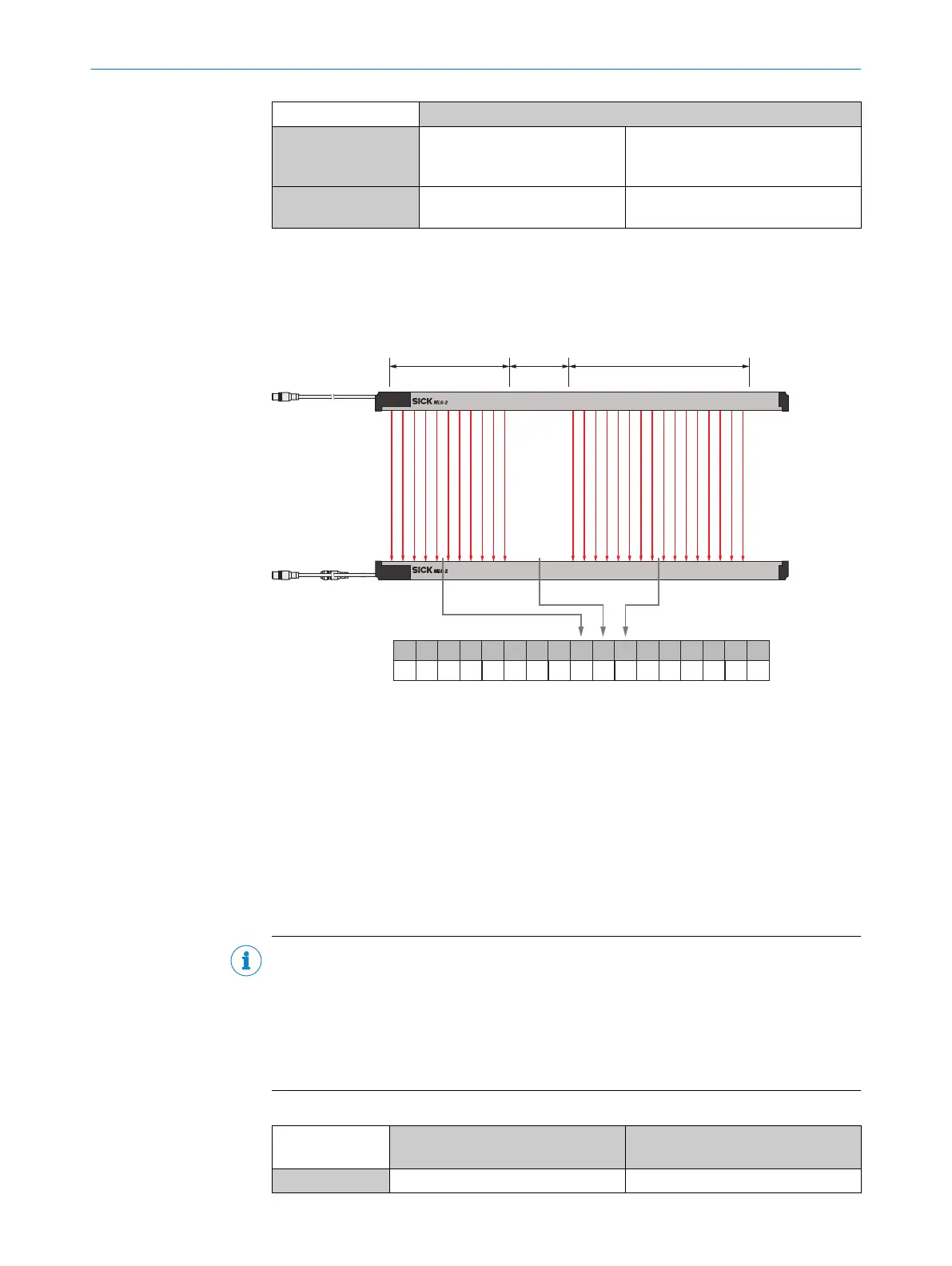
Figure 6: Configuring MLG-2 measurement field width using type code
1
Head side measurement field width and number of head side measurement modules
2
Blind zone and number of empty modules
3
Connection side measurement field width and number of connection side measurement
modules
T
he measurement field width is calculated from the ordered module number. Positions
9 to 11 r
epresent the module number in the type code.
The module width is always 150 mm. The largest possible measurement field with of
3,150 mm results from the possible module number of 21. The smallest possible mea‐
surement field width is a measurement module with 150 mm.
NOTE
A maximum of 16 me
asurement modules can be used in one MLG-2 WebChecker. The
light grid can be filled with empty modules. A maximum of 19 empty modules may be
used and the total number of modules must not exceed 21.
There must be at least one measurement module on the connection side and on the
head side. If no empty modules are used, all active modules on the terminal compart‐
ment must be specified.
Table 4: Measurement field width
Position 8 - 11 Meaning Type code specification -
Number whic
h can be ordered
8 No selection –
3 PRODUCT DESCRIPTION
14
O P E R A T I N G I N S T R U C T I O N S | MLG-2 WebChecker 8025190/2020-01-13 | SICK
Subject to change without notice