ß
LEDs on the control panel
à
Teach pushbut
t
on
The teach-in process for the MLG-2 can be started by pressing the Te
ach pushbutton.
The pushbutton can be locked to prevent incorrect operation. The lock can be activated
and deactivated via SOPAS ET, using the fieldbus functions, or by pressing the pushbut‐
ton.
Locking the control panel
1. Press the Teach pushbutton for 15 s.
✓
The control panel is locked; the configuration cannot be changed.
✓
If a pushbutton is pressed on the control panel, the Alignment LED lights up.
Disabling the lock
1. Press the Teach pushbutton for 15 s.
✓
The lock is disabled.
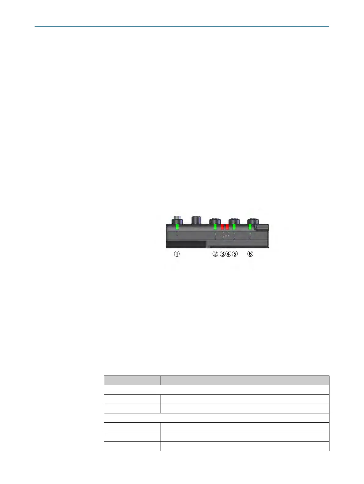
3.8.2 Fieldbus module
The fieldbus module has six LEDs.
T
he sec
tion Troubleshooting on page 106 explains the meaning of the LED indicators.
Figure 11: LEDs on the fieldbus module
1
POWER
2
LINK/ACT
3
BF/ERR/NS
4
SF/RUN/MS
5
LINK/ACT
6
LINK/ACT
3.8.2.1 Status indicator of the fieldbus module
PROFINET
T
able 8
: LEDs on the fieldbus module
LED Meaning
POWER
O
Supply voltage on
o
Supply voltage off or too low
LINK/ACT
O
Ethernet connection present
o
No Ethernet connection
Ö 1 Hz
Data is being received or sent
PRODUCT DESCRIPTION 3
8025190/2020-01-13 | SICK O P E R A T I N G I N S T R U C T I O N S | MLG-2 WebChecker
21
Subject to change without notice