3
Graphic display and histogram of the calculated width (colored line shown thicker)
11.4 Enhanced Sensing – menus
11.4.1 “Sensor alignment” menu
Start the "Installation assistant” wizard using this menu. You will be guided through the
entir
e wizard with the "Sensor alignment", "Sensor teach-in" and "Material teach-in”
steps.
More information:
•
“Installation assistant” wizard: see "Setting up MLG-2 WebChecker (installation
assistant)", page 55
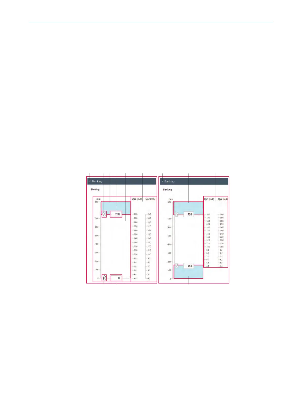
11.4.2 “Blanking” menu
You can limit the measurement field width of the MLG-2 with this menu. To do so, either
blank onl
y an ar
ea on the connection side or on the head side or blank areas on both
sides. The 4 mA value and the 20 mA value of the current output are automatically
assigned to the upper and lower measurement field limit.
Example for blanking
Figure 68: “Enhanced Sensing” page, “Blanking” menu (2 examples)
1
Example with one-sided blanking (from the head side)
2
Example with blanking on both sides
3
Slider for upper measurement field limit
4
Input field for upper measurement field limit
5
Measurement field width with one-sided blanking
6
Analog outputs with blanking on both sides, only for MLG-2 variants with analog outputs
7
Analog outputs with blanking, only for MLG-2 variants with analog outputs
8
Blanked areas (shown in blue)
9
Input field for lower measurement field limit
ß
Slider for lower measurement field limit
11 C
ONFIGURATION WITH SOPAS
96
O P E R A T I N G I N S T R U C T I O N S | MLG-2 WebChecker 8025190/2020-01-13 | SICK
Subject to change without notice