Conditions for determining the accuracy of the actual object position:
•
We
b sheet in optimal object position
•
Fluctuation in read direction < ± 100 mm
•
Constant ambient temperature
Determining measurement accuracy for actual object position
1. Select characteristic for the distance between sender and receiver in the diagram.
Example: Characteristic "d" for 1,000 mm
2. Identify optimal object position. Example: 678.0 mm
3. Identify actual object position. The actual object position is the actual distance
between object and sender. Example: 648.0 mm
4. Calculate difference between the optimal object position and the real object posi‐
tion.
Example: 648.0 mm – 678.0 mm = –30 mm
5. Identify accuracy using the diagram.
Example: ± 0.48 mm
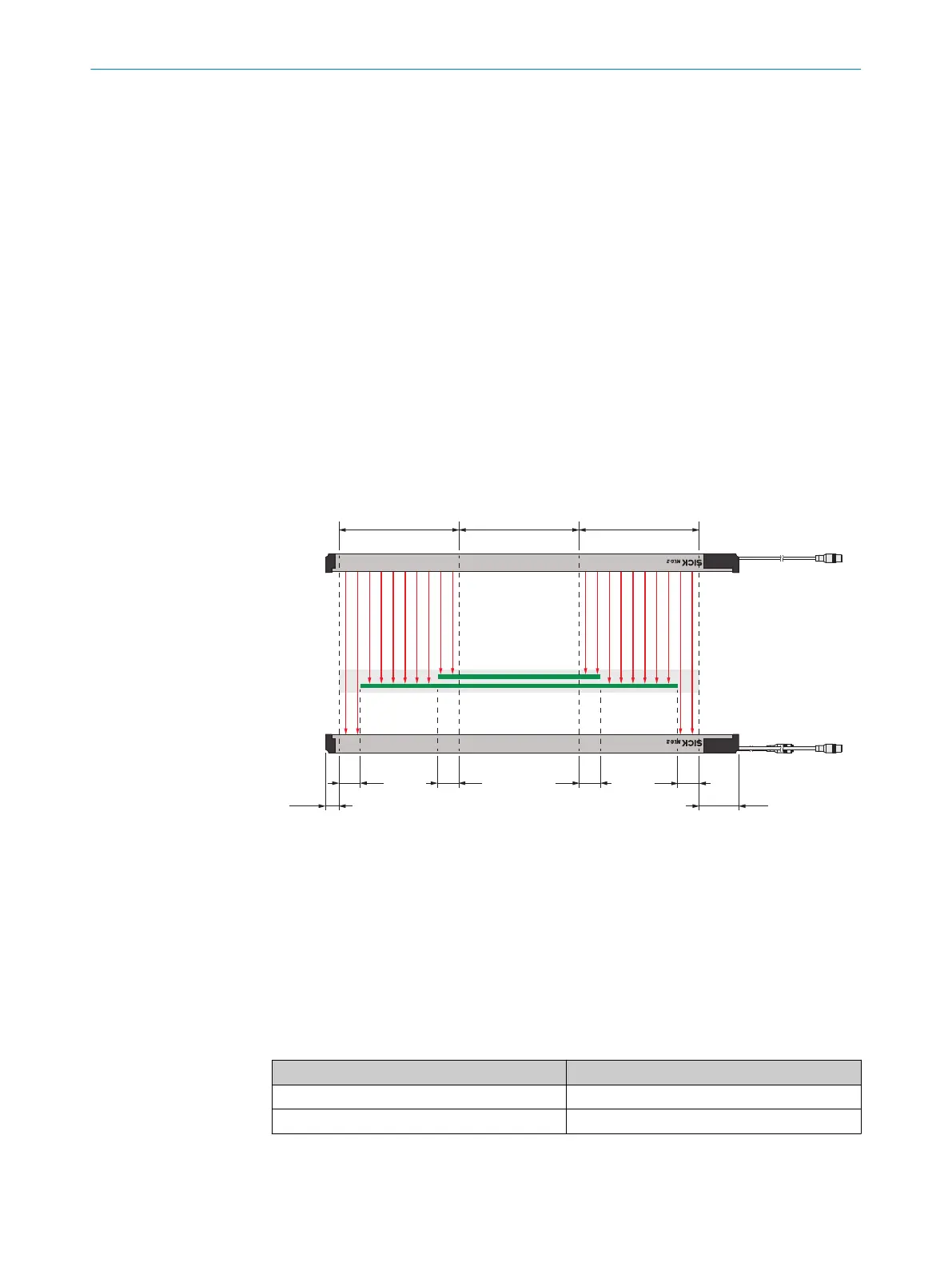
4.4 Required minimum distances for an object
You must comply with the following minimum distances for an object:
•
Measurement field border - edge
rs
min
max
4
5
3
1
2
A
6
2
8
13,5
A A A
6
7
Figure 21: Object widths (example of MLG-2 with empty modules)
1
Head side measurement modules
2
Empty modules
3
Connection side measurement modules
4
Minimal object width with empty modules arranged in the center
5
Maximum object width
6
A: Necessary distance between measurement field border - edge
7
Head side blind zone
8
Connection side blind zone
Table 13: Required distance A
Description Distance A (measurement field border - edge)
Typical distance 23 mm
Minimum distance under ideal conditions
1
8 mm
1
Ideal conditions: Homogeneous material, optimal ambient conditions and optimal object position
4 PLANNING
28
O P E R A T I N G I N S T R U C T I O N S | MLG-2 WebChecker 8025190/2020-01-13 | SICK
Subject to change without notice