0 mm
5
0 mm
100 mm
150 mm
0.0 m 2.0 m
X
Operating range
Minimum distance
Y
Figure 27: Graph of minimum distance from reflective surfaces
5.3 Mounting procedure
Additional information
•
see "Plannin
g mounting distance between sender and receiver", page 25
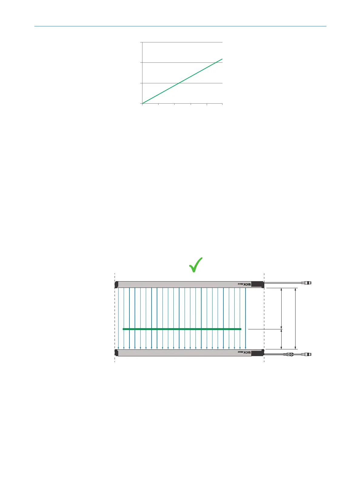
Observe the following points for correct mounting:
•
Align sender and receiver with the front screens toward one another with a water
level.
•
Connecting cables from the sender and receiver must point in the same direction.
•
The head sides of the sender and the receiver must be aligned.
•
Mount the sender and receiver such that the object to be detected is placed at an
optimal object position. The optimal object position is the distance between the
sender and the object and is about 2/3 of the distance between the sender and
receiver, see figure 19, page 26.
•
Observe operating range.
rs
ca. 1/3
ca. 2/3
max. 2.5 m
2
2
1
Figure 28: Correct mounting
1
Operating range: Maximum possible distance between sender and receiver
2
Optimal object position, approximate specifications
MOUNTING 5
8025190/2020-01-13 | SICK O P E R A T I N G I N S T R U C T I O N S | MLG-2 WebChecker
35
Subject to change without notice