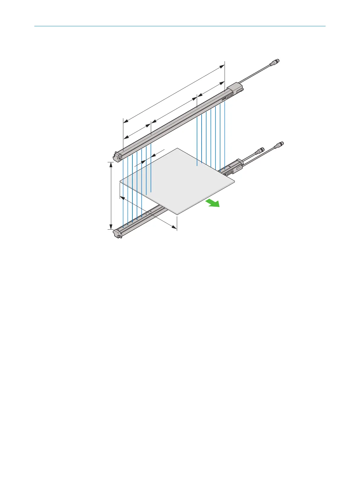
3.4 Definitions
Figure 8: Definitions for MLG-2
1
Distance between sender and receiver
2
Measurement field width
3
Area with measurement modules on the head side (left)
4
Area with empty modules
5
Area with measurement modules on the connection side (right)
6
Sender
7
Receiver
8
Beam separation
9
Minimum object length (shown longer here)
Scanning ranges
The oper
ating range is the distance between sender and receiver for which the MLG-2
works safely. The operating range is 2.5 m and takes into account an operating reserve.
Measurement field width
The MLG-2 consists of measurement modules and optionally empty modules. The mea‐
surement modules can be located on the connection side and on the head of the
MLG-2. Empty modules do not have LEDs.
The measurement field width is calculated from the ordered module number. Positions
9 to 11 represent the module number in the type code.
Additional information
•
Type code: see "Measurement field width", page 14
3 P
RODUCT DESCRIPTION
18
O P E R A T I N G I N S T R U C T I O N S | MLG-2 WebChecker 8025190/2020-01-13 | SICK
Subject to change without notice