Chapter 5
MSC800
8011540/14B8/2019-06-06 Operating instructions | SICK 47
Subject to change without notice
MSC800-2300
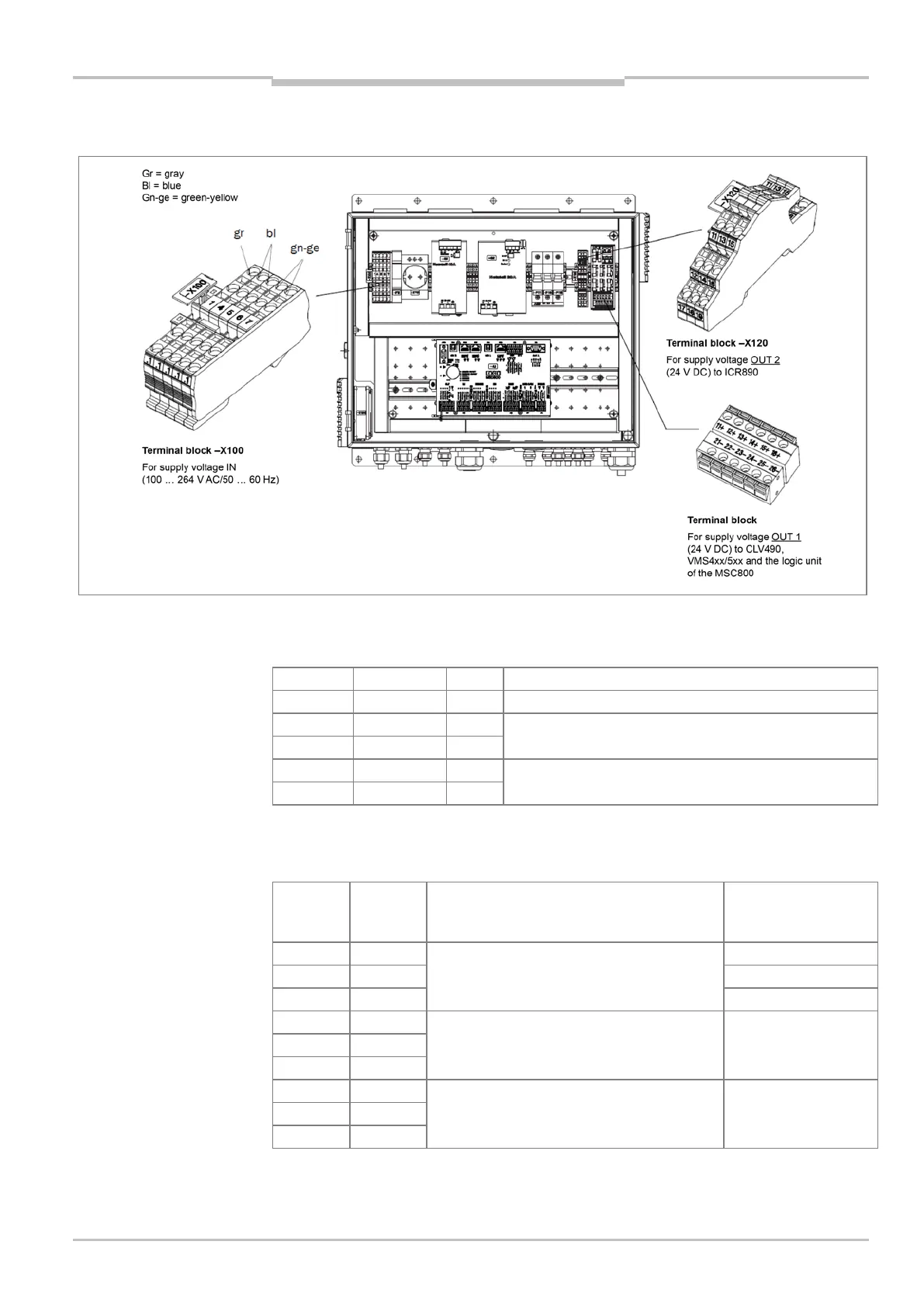
Fig. 19: Terminals on the MSC800-2300 for mains voltage IN and supply voltage OUT
Connections for mains voltage IN on the MSC800-2300
Terminal Color Signal Function
Mains voltage AC 100 ... 264 V / 50 ... 60 Hz (phase)
Mains voltage AC 100 ... 264 V / 50 ... 60 Hz (neutral
conductor)
-X100/1.5 Blue N
-X100/1.6 Green-yellow PE Protective conductor
Tab. 15: MSC800-2300: -X100 terminal block pin assignment for mains voltage IN
Connections for supply voltage OUT 2 on the MSC800-2300 for ICR890
Terminal Signal Function Protected by the
automatic circuit
breakers
-X120/11 DC +24 V Supply voltage OUT 2 (power supply unit
module 2)
–F111
-X120/12 GND Ground (power supply unit module 2) –
-X120/14 GND
-X120/16 GND
Shield -
-X120/18 Shield
-X120/19 Shield
Tab. 16 MSC800-2300: assignment of the -X120 terminal block for
supply voltage OUT 2 on ICR890