Chapter 5
MSC800
8011540/14B8/2019-06-06 Operating instructions | SICK 49
Subject to change without notice
MSC800-3400
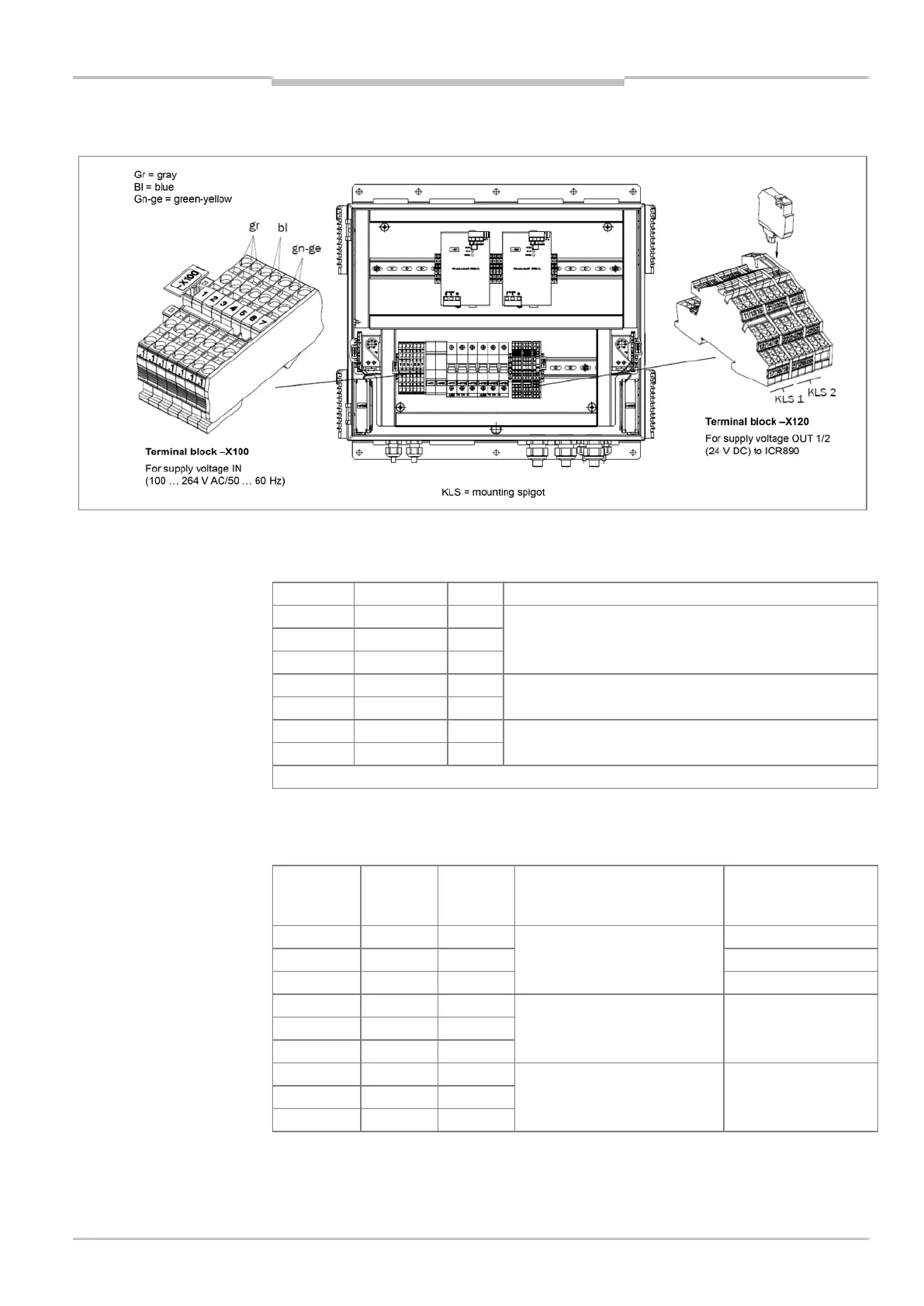
Fig. 20: Terminals on the MSC800-3400 for mains voltage IN and supply voltage OUT
Connections for mains voltage IN on the MSC800-3400
-X100/1.1 Gray L Mains voltage AC 100 ... 264 V / 50 ... 60 Hz (phase)*
-X100/1.2 Gray L
-X100/1.3 Gray L
Mains voltage AC 100 ... 264 V / 50 ... 60 Hz (neutral
conductor)
-X100/1.5 Blue N
-X100/1.6 Green-yellow PE Protective conductor
-X100/1.7 Green-yellow PE
After removing the bridge between the gray terminals, the assignment also has three different phases
Tab. 18: MSC800-3400: -X100 terminal block pin assignment for mains voltage IN
Connections for supply voltage OUT 1 and OUT 2 on the MSC800-3400
Terminal
set
Terminal Signal Function Protected by the
automatic circuit
breakers
Supply voltage OUT 1 (power
supply unit modules 1)
-X120/15 DC +24 V –F115
-X120/12 GND Ground 1 –
-X120/14 GND
-X120/17 Shield Shield –
-X120/18 Shield
-X120/19 Shield
Tab. 19 MSC800-3400: assignment of the -X120 terminal block, part 1 for
supply voltage OUT 1 on ICR890 (system 1)