Chapter 5
MSC800
50 Operating instructions | SICK 8011540/14B8/2019-06-06
Subject to change without notice
KLS2 -X120/21 DC +24 V Supply voltage OUT 2 (power
supply unit modules 2)
–F121
–F123
–F125
-X120/22 GND Ground 2
-X120/24 GND
Shield –
-X120/28 Shield
-X120/29 Shield
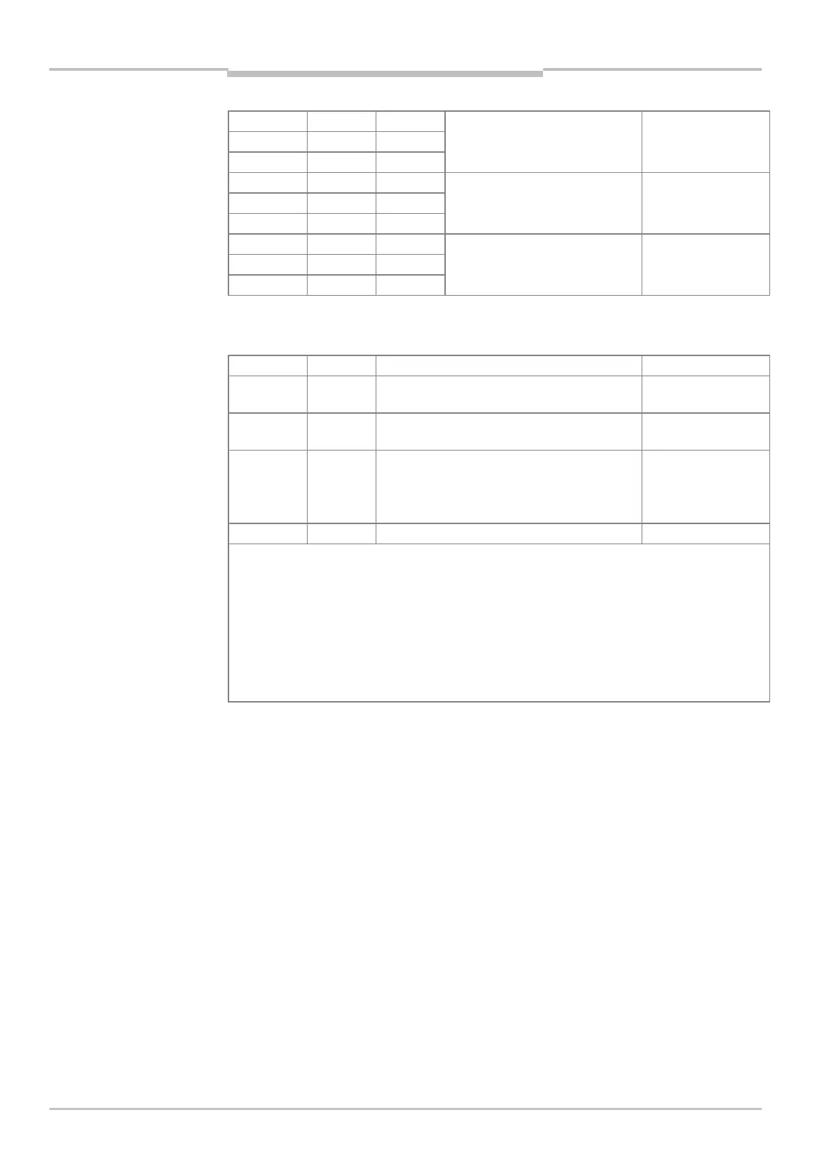
Tab. 20 MSC800-3400: assignment of the -X120 terminal block, part 2 for
supply voltage OUT 2 on ICR890 (system 2)
Terminal Signal Function Protected by fuse
-X120/41 + Measuring point thermal circuit breaker 1
1)
–
-X120/42 – Measuring point thermal circuit breaker 1
1)
–
-X120/51 DC +24 V Supply voltage OUT 1
(power supply unit module 1, tap before circuit
breaker F111/113/115) on thermal circuit
breaker 2 (blue)/fan 1 and 2
F1 (4 A, slow-acting)
-X120/52 GND Ground –
1)
Thermal circuit breaker, left in the MSC800-3400 (see MSC800-3400 device view on page 22), switch
opens at T
U
= 57.5 °C.
By setting up a closed circuit (DC +24 V on terminal -X120/41; GND on terminal -X120/42) and using
appropriate assessment, e.g., by the logic unit of an MSC800, it is possible to signal overheating of the
cabinet. It is also possible to use series connection of the same thermal circuit breaker to MSC800 cabinets
of the same type.
2)
Thermal circuit breaker, right in the MSC800-3400 (see MSC800-3400 device view on page 22), switch
U
= 37.5 °C and switches the two fans on/off.
Tab. 21 MSC800-3400: assignment of the -X120 terminal block, part 3 for
supply voltage OUT 1 on thermal circuit breaker/fan