Specification of Drive Functions
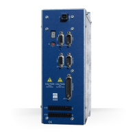
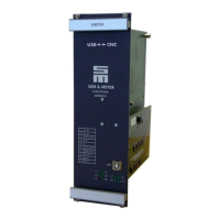
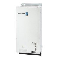
107Drive System SD2M - Hardware Description 036228xxF
Drive function SERVO / VECTOR VF
SVC:
▶ Synchronous rotative
▶ Up to 2000 Hz rotating field frequency
Software
Drive function SERVO / VECTOR VF
Software pack-
ages
(1)
▶ L13001Vxxxxx & F13001Vxxxxx
(1)
After the firmware and logic software have been detected, the SD2M software packages can be iden-
tified by the number '13' contained in the software designation (e.g. logic software = L13xxx, firmware =
F13)xxx.
Measuring system
Drive function SERVO / VECTOR VF
Measuring systems L13001 / F13001
▶ Sensorless vector control (SVC)
L13001 / F13001
▶ Sensorless
▶ Field plate 2-wire
▶ Field plate 3-wire
▶ Pulse generator NAMUR
▶ Pulse generator 24 V
▶ Pulse generator 5 V
▶ Digital field plate / GMR
Operating mode
Drive function SERVO / VECTOR VF
Operating modes ▶ Speed Mode
▶ Current reference value
▶ Profile Velocity Mode
▶ Interpolated position control
▶ Electronic gear
▶ Speed Mode
Software Connection
Drive function SERVO / VECTOR VF
Parameterization in soft-
ware drivemaster2
▶ USB connection
▶ RS232 connection
▶ SERVOLINK 4 (only optical fibers)
Communication channels
Drive function SERVO / VECTOR VF
Control channel ▶ Digital inputs
▶ Serial interface / RS485 / USB
▶ SERVOLINK 4
▶ CAN Bus
▶ DNC 8 Byte Telegram
Setpoint channel ▶ Analog inputs
▶ Serial interface / RS485 / USB
▶ Internal setpoints
▶ Encoder 0
▶ SERVOLINK 4
▶ CAN Bus
▶ DNC 8 Byte Telegram
▶ Analog inputs
▶ Serial interface / RS485 / USB
▶ Internal setpoints
▶ SERVOLINK 4
▶ CAN Bus
▶ DNC 8 Byte Telegram


 To Next Page