108/245
Building Technologies Division Basic Documentation LME7... CC1P7105en
Infrastructure & Cities Sector 16 PME73.820... 29.11.2011
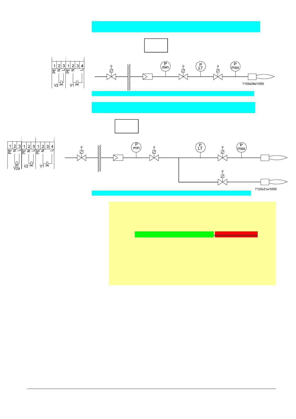
16.2.3 Gas direct ignition 1 (G), 1-stage, with valve proving
SV
V1
Program
G
Gas direct 1-stage, with valve proving
X7-04
LME73.000...
V2
X7-02
Figure 49: Connection diagram fuel train gas direct ignition 1 (G), 1-stage, with valve proving
16.2.4 Gas direct ignition (G), 2-stage, with valve proving
SV
V1
Program
G
Gas direct 2-stage, with valve proving
X7-01
LME73.000...
V2a
V2
X7-02 X7-04
Figure 50: Connection diagram fuel train gas direct ignition (G), 2-stage, with valve proving
Note:
When valve proving is activated (e.g. on shutdown), the load on the valve’s
terminals (according to chapter Technical data/Terminal rating Outputs) is
restricted.
Fuel valve 1 X7-04 pin 4/fuel valve 2 X7-02 pin 3/auxiliary output AUX
Rated voltage AC 120 V AC 230 V
50/60 Hz 50/60 Hz
Rated current 1 A 1 A
Power factor cos >0.4 cos >0.4
If the terminal load (according to chapter Technical data/Terminal rating
Outputs) is not reduced (max. rated current 2 A, cos >0.4), the design
lifetime will be reached after about 100,000 burner startup cycles!

 Loading...
