55/245
Building Technologies Division Basic Documentation LME7... CC1P7105en
Infrastructure & Cities Sector 11 PME71.402... 29.11.2011
11 PME71.402...
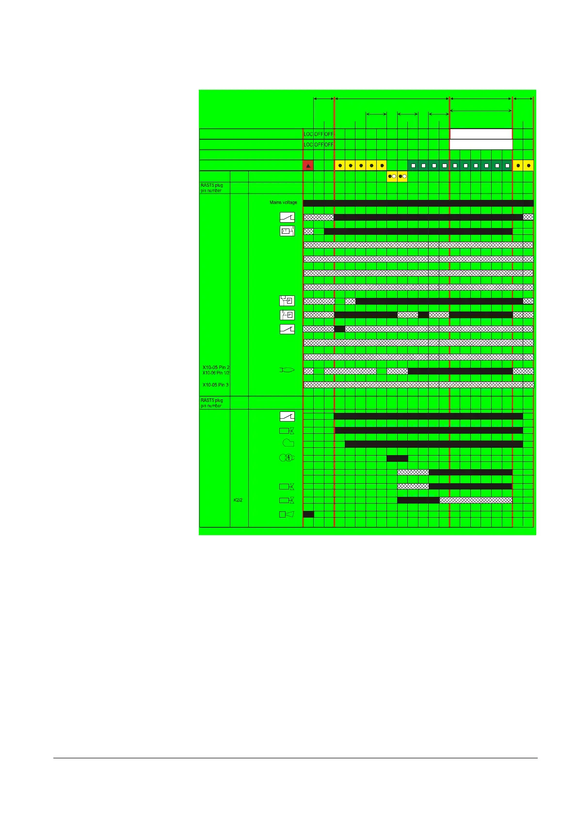
11.1 Program sequence PME71.402...
For connection diagram fuel trains (G)/(Gp1/1)
7105d70e/0611
M
Z
V1
PV
AL
K1X2-02 Pin 3
R
Not active
LP
Pmin
ION / QRA
X3-04 Pin 5
Relay
contact
Function / inputs
Display and operation unit parameter number
LED permanent
LED flashing
tw t10 t3 t3n t4 t8
Standby Startup Operation
Shutdown
t1
TSA
224 225 226 257 231 240 234
Relay
contact
Function / outputs
SK
X3-04 Pin 1
X5-03 Pin 1
X5-03 Pin 3
X65 Pin 1
X5-03 Pin 2
X65 Pin 1
X3-02 Pin 1
X5-01 Pin 2
X2-02 Pin 4
X9-04 Pin 2
SV
K1X6-03 Pin 3
K4X2-01 Pin 3
K5X4-02 Pin 3
K7X7-04 Pin 4
X7-01 Pin 3
K2/1X2-03 Pin 3
Phase number AZL2...
21 22 22 30 30 38 40 42 44 74 10
X2-02 Pin 4
240240 240 240 240
oP:P1
Phase number 7 segment in the LME...
21 22 22 30 30 38 40 42 44 74 10oP1
Not active
Not active
POC
Not active
Not active
Not active
POC
50 50
Repetition in the event of
loss of flame during
operation (depending on
parameter 240)
Not active
Input
K7X7-04 Pin 3
t9
50 50
t22
K1
Figure 17: Program sequence PME71.402... for connection diagram fuel trains (G)/Gp1/1)

 Loading...
