88/245
Building Technologies Division Basic Documentation LME7... CC1P7105en
Infrastructure & Cities Sector 14 PME72.541... 29.11.2011
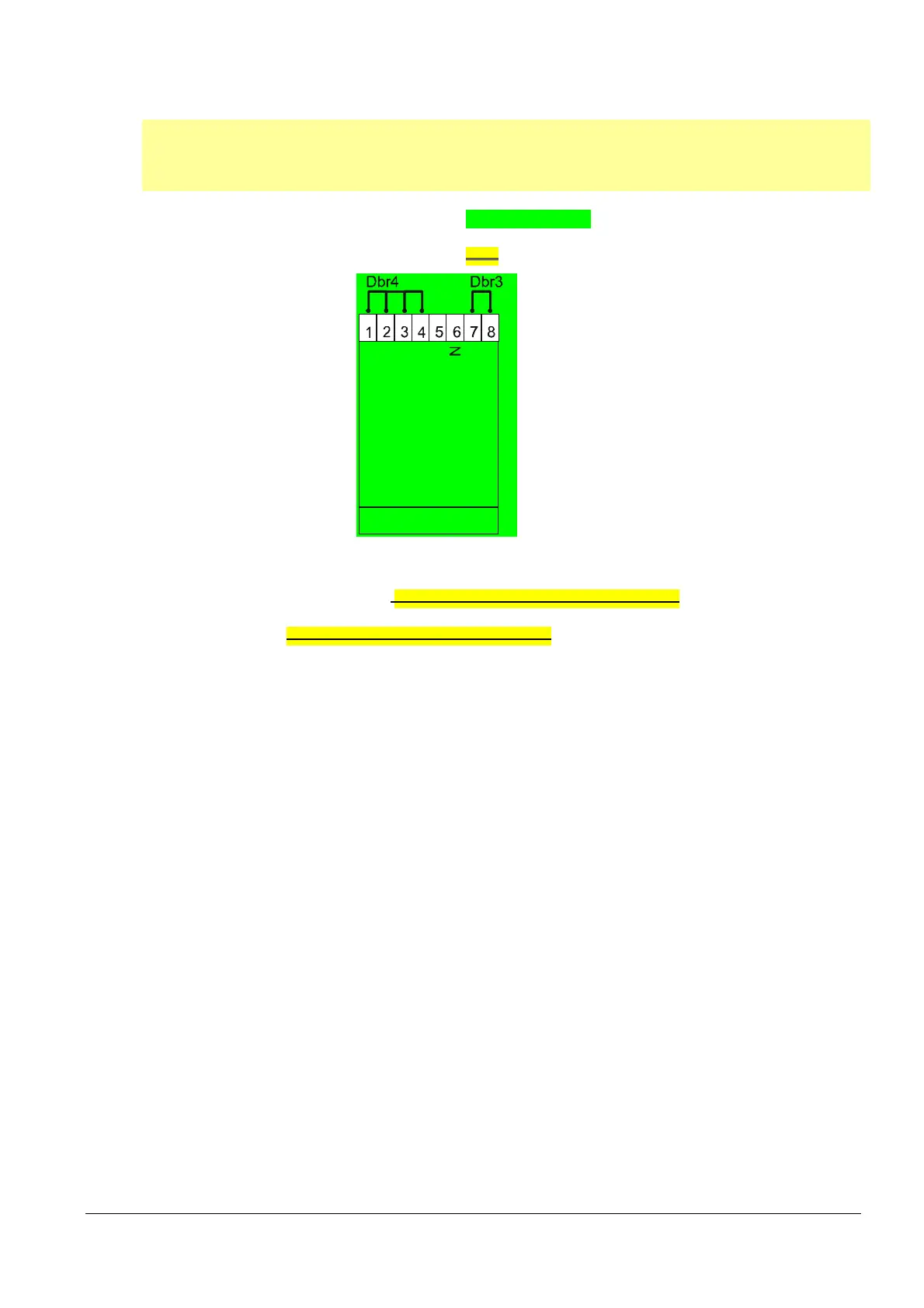
14.4 Connection diagram for LME72.000... without
actuator SQM4...
Note:
The connection diagram shown is merely an example which must be verified in the individual case
depending on the application!
PME72.541... 1-stage
With pilot ignition
Without actuator
With/Without valve proving
X2-09
SA-Z
SA-KL
SA-NL
SA-R
PE
Input pilot valve PV
Output pilot valve PV
7105d85e/1111
Figure 36: Connection diagram for LME73.000... without actuator SQM4...
When using the LME72.000... without actuator according to application Gas direct
ignition (G), 1-stage or gas direct ignition 1 (G), 1-stage, with valve proving, wire
link Dbr4 must be fitted to the actuator’s X2-09 as shown above
Parameter P515.01 must be set to 0

 Loading...
