164/245
Building Technologies Division Basic Documentation LME7... CC1P7105en
Infrastructure & Cities Sector 21 Multistage or modulating mode 29.11.2011
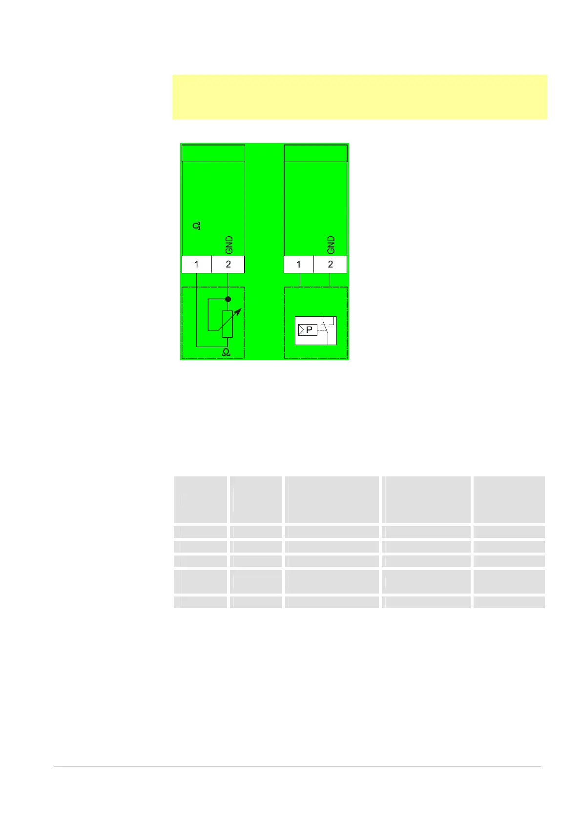
21.1.2 Connection diagram for load controller
Note:
The connection diagram shown is merely an example which must be verified in the
individual case depending on the application!
PME7...
X65
0-135
7105d40/1210
0-135
X65
0-10V
0-20mA
4-20mA
LR
Figure 85: Connection diagram for load controller
21.2 Actuators
The LME7... has terminals for the connection of electromotoric actuators for the control
of air dampers and regulating dampers of oil and gas burners.
Possible types of actuator:
Type
Data
Sheet
Operating mode ¹)
stage/modulating
via 3-position step
input X5-03
Operating mode ¹)
modulating via
analog input
signal X65
Potentiometer
ASZxx.3x
SQN3... N7808 x x x
SQN7... N7804 x x x
SQM2... N7812 x x x
SQM40...
SQM41...
N7817 x x x
SQM5... N7815 x x x
¹) Depending on the program sequence of LME7... or in the PME7...
21.3 Function
The internal program cycle time of the LME7... is about 0.147 s ( 0.15 s).
In each
program sequence, each input is read and the outputs are switched on or off
accordingly.

 Loading...
