48/245
Building Technologies Division Basic Documentation LME7... CC1P7105en
Infrastructure & Cities Sector 10 PME71.401... 29.11.2011
10 PME71.401...
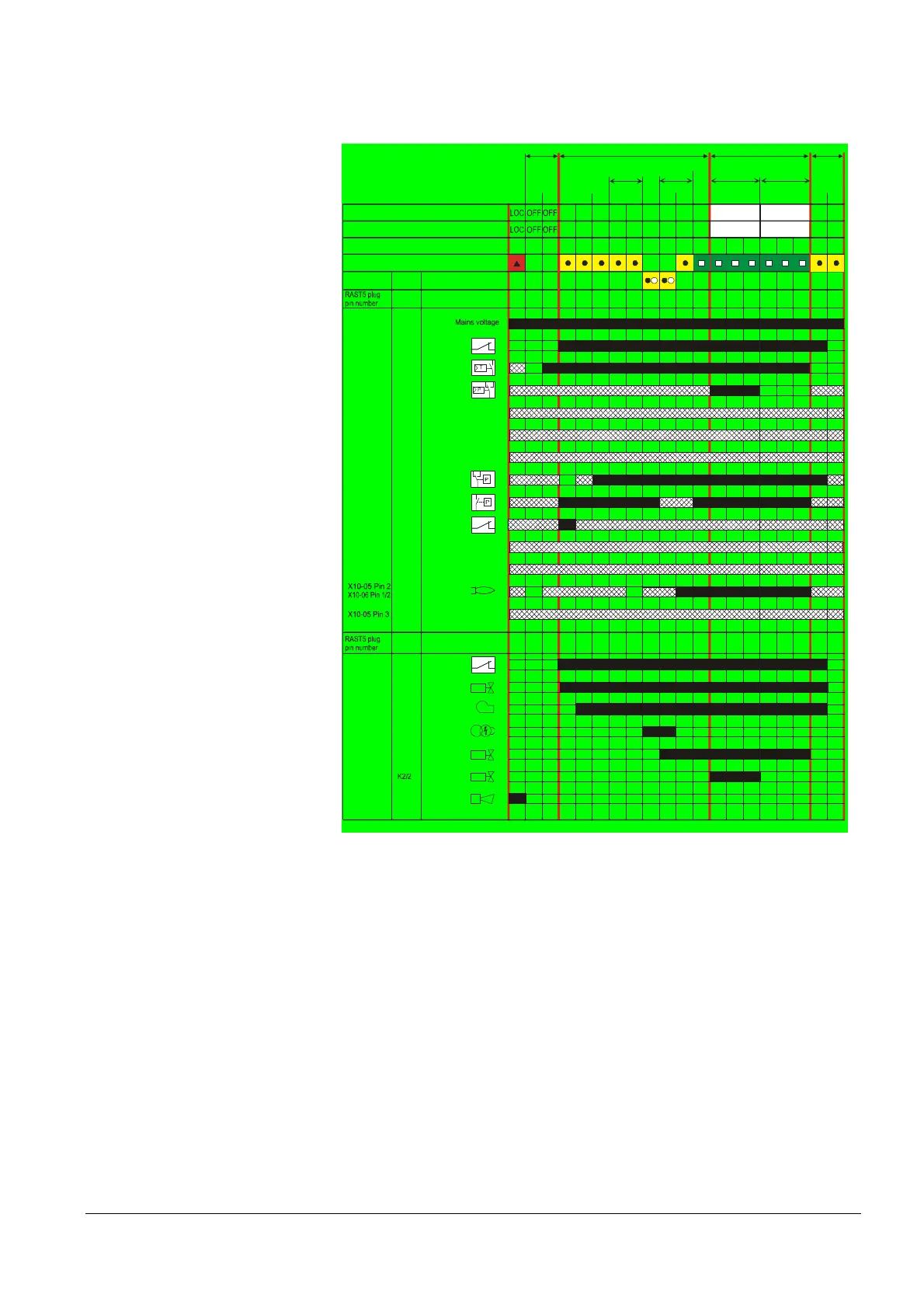
10.1 Program sequence PME71.401...
For connection diagram fuel train (G)
7105d69e/0611
M
Z
V1
V2a
AL
K1X2-02 Pin 3
R
LR-OPEN
Not active
LP
Pmin
ION / QRA
X3-04 Pin 5
Relay
contact
Function / inputs
Display and operation unit parameter number
LED permanent
LED flashing
tw t10 t3 t3n t4 t8
Standby Startup Operation Shutdown
t1
TSA
224 225 226 257 230 240 234
Relay
contact
Function / outputs
SK
X3-04 Pin 1
X5-03 Pin 1
X5-03 Pin 3
X65 Pin 1
X5-03 Pin 2
X65 Pin 1
X3-02 Pin 1
X5-01 Pin 2
X2-02 Pin 4
X9-04 Pin 2
SV
K1X6-03 Pin 3
K4X2-01 Pin 3
K5X4-02 Pin 3
K7X7-04 Pin 4
X7-01 Pin 3
K2/1X2-03 Pin 3
Phase number AZL2...
21 22 22 30 30 38 40 42 44 74 10
X2-02 Pin 4
240240 240 240 240
oP:P2 oP:P1
Phase number 7 segment in the LME...
21 22 22 30 30 38 40 42 44 74 10oP2 oP1
Not active
Not active
POC
Not active
Not active
Not active
POC
2nd stage 1st stage
Figure 13: Program sequence PME71.401... for connection diagram fuel train (G)

 Loading...
