206/245
Building Technologies Division Basic Documentation LME7... CC1P7105en
Infrastructure & Cities Sector 25 Operation via internal LED 29.11.2011
25.4 Fault status messages, display of errors
25.4.1 Display of errors (faults) with lockout
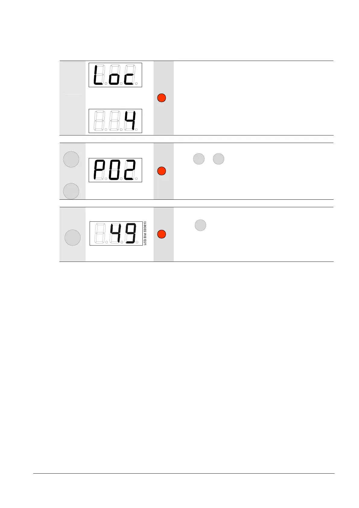
LCD Bild 06/0908
Alternately
LCD Bild 07/0908
Display shows alternately Loc and 4.
Unit is in the lockout position.
The current error code is displayed and the signal lamp is
blinking red.
Example: Error code 4
+
or
-
LCD Bild 08/0908
Press
+
or
-
for display of the phase, where the fault
appeared.
Signal lamp blinks red.
Example: Phase P02
A
Only with modulation via analog signal
Press
A
for display of the output position/actuator
position where the error occurred.
Signal lamp lights up red.
Example: Output position/actuator position 49

 Loading...
