133/245
Building Technologies Division Basic Documentation LME7... CC1P7105en
Infrastructure & Cities Sector 18 PME73.831… 29.11.2011
710 5d 67e /1111
M
Z
V1
V2
AL
K1X2-02 Pin 3
Actuator position
High-fire
Ignition load
Low-fire
CLOSE
R
LR-OPEN
LR-CLOSE
LP
Pmin
P LT
ION / QRA
QRB / QRC
X3-04 Pin 5
Relay
contact
Function / inputs
Display and operating unit parameter number
LED permanent
LED flashing
tw t11 t10 t12 t3 t3n t4 t8 td4 td1 td3 td2
Standby Startup Operation Shutdown Valve proving *4
If parameter
P241 =1 (ON)
Can be
parameterized
t1
TSA
259 225 226 257 230 231 260 232 234
Relay
contact
Function /outputs
SK
X3-04 Pin 1
X5-03 Pin 1
X5-03 Pin 3
X65 Pin 1
X5-03 Pin 2
X65 Pin 1
X3-02 Pin 1
X5-01 Pin 2
X2-02 Pin 4
X9-04 Pin 2
PV
SV
K1X6-03 Pin 3
K4X2-01 Pin 3
K5X4-02 Pin 3
K2/2X7-01 Pin 3
K7X7-04 Pin 4
X7-02 Pin 3
K2/1X2-03 Pin 3
Phase number
21 22 24 22 30 30 36 38 40 42 44 50 54 72 74 10 80 81 82 83
oP1
t9 t12 t5
SA-NL
K11X2-09 Pin 3
SA-KL
K12X2-09 Pin 2
SA-ZU
X2-09 Pin 1
SA-R
X2-09 Pin 4
Output SA-ZL cams
K2/2X2-09 Pin 7
Input SA-ZL cams
X2-09 Pin 8
X2-02 Pin 4
*3
*1 *2
*3
24
t12
260
36
260
oP:xx
(actual power in %)
*1
*2
*) *) *) *) *)
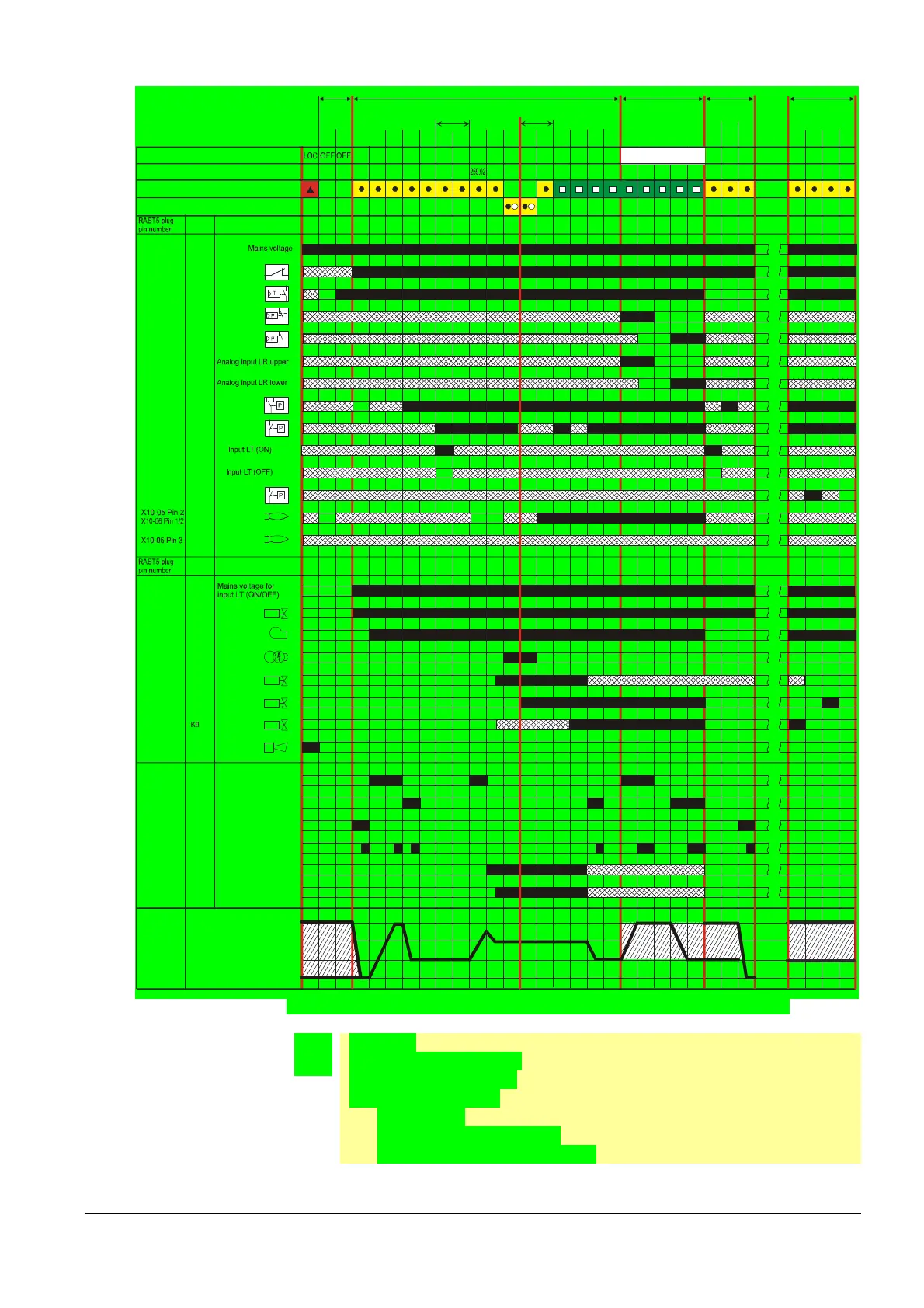
Fig. 66: Program sequence PME73.831... to connection diagram fuel trains (G)/(Gp1)/(Gp2)
Version 4:
Ignition load > low-fire
Prepurging in low-fire
Parameter 515 = 0
(requirement:
- parameter 259.01 = 0 and
- parameter 259.02 > 0 seconds)

 Loading...
