• 2 properly executed drill holes with thread or plugs on the level surface.
The 3RW5 communication module must be mounted to the left of the 3RW50 soft starter.
Observe the position of the 3RW5 communication module in the drilling pattern (Page 148).
The COM connecting cable has a limited length.
• 2 head screws M4 x 12 DIN ISO 7045 to t the drill-holes
• Screwdriver (depending on the drive of the screws)
• 2 push-in lugs (accessories) for wall mounting (Page 36)
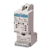
Illustration similar
Mounting and dismantling
4.3 Installing the 3RW5 communication module on a level surface
SIRIUS 3RW5 PROFINET communication modules
42 Equipment Manual, 05/2021, A5E35631297002A/RS-AD/004

 Loading...