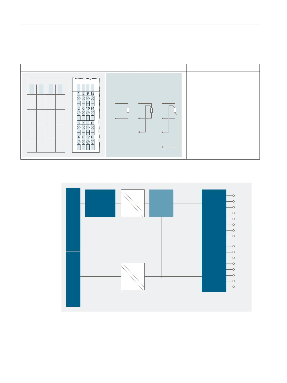
Pin assignment
Table 14-6 Pin assignment of the 4 AI RTD
Pin assignment and view Remarks
$POOFDUJPOFYBNQMFGPS
DIBOOFM
$IBOOFM
DPOEVDUPSXJSFXJSF
.
.
.
.
....
*$
*$
*$
*$
*$*$*$*$
Resistance thermometer 1
Channel 0: Terminals 1 to 4
Resistance thermometer 2
Channel 1: Terminals 5 to 8
Resistance thermometer 3
Channel 2: Terminals 9 to 12
Resistance thermometer 4
Channel 3: Terminals 13 to 16
M+: Measuring cable (positive)
M-: Measuring cable (negative)
I
C
+: Constantcurrent cable (positive)
I
C
-: Constant-current cable (negative)
Block diagram
#BDLQMBOFCVT
DPOOFDUJPO
1PXFSCVT#BDLQMBOFCVT
.VMUJQMFYFS
$POWFSUFS
*OQVUT
u$
Figure 14-3 Block diagram of the 4 AI RTD
Analog electronic modules
14.4 Analog electronics module 4 AI RTD
ET 200iSP
358 Operating Instructions, 11/2022, A5E00247483-AK