Function blocks
2.1 Function blocks - input and output types, structure
SIMOCODE pro - Parameterize
14 Operating Manual, 04/2017, A5E40507630002A/RS-AA/001
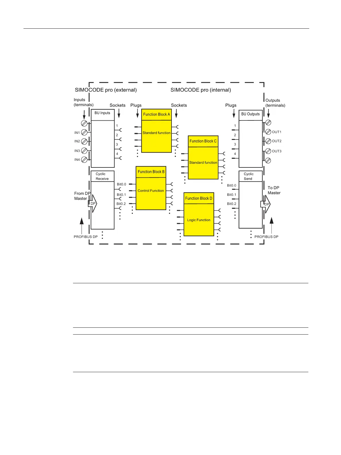
Diagram of basic structure
The following function block diagram (example) shows the basic structure of SIMOCODE pro
with its external inputs and outputs and internally stored function blocks:
Figure 2-1 Basic structure of SIMOCODE pro
Connecting plugs with sockets
Note
The function block plugs and sockets have not
already been connected at the factory with
the binary inputs and the relay outputs of the basic unit.
The internal wiring (connection between plugs and sockets) is determined by the selected
application.
1)
Note
When you have already installed external wiring, but have not yet parameterized
SIMOCODE
pro:
If you press a button now, the contactors will not be energized.
1)
1) If you select and load a preset application (e.g. the reversing starter) in SIMOCODE ES,
all links and interlocks for the reversing starter will be set up in the basic unit.