EasyManuals Logo

Siemens SIMOCODE pro Operating Manual

Siemens SIMOCODE pro
278 pages
To Next Page IconTo Next Page
To Previous Page IconTo Previous Page
Page #189 background imageLoading...
Page #189 background image
Parameters
4.5 Inputs
SIMOCODE pro - Parameterize
Operating Manual, 04/2017, A5E40507630002A/RS-AA/001
189
Schematic
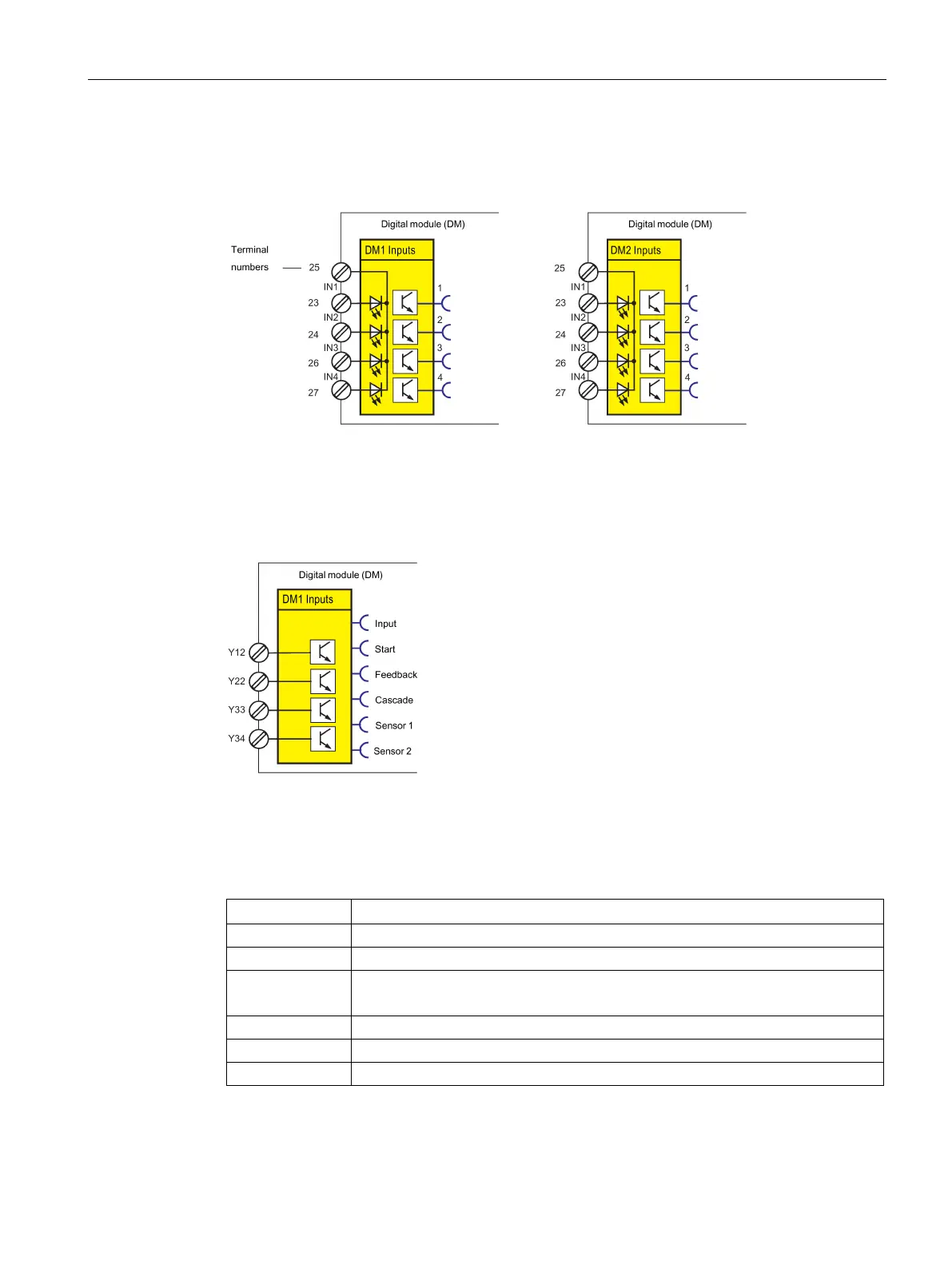
The following schematic shows the "DM1 / DM2 Inputs" function blocks:
Figure 4-64 Schematic of the "DM1 / DM2 Inputs" function blocks
The following schematic shows the "DM1 Inputs" function block as fail-safe digital module
DM-F Local:
Figure 4-65 The following schematic shows the "DM1 Inputs" function block as fail-safe digital
module DM-F Local
Table 4- 60 The following schematic shows the "DM1 Inputs" function block as fail-safe digital
module DM-F Local
Input
Description
Input
1 - "tripped" state
Start
Start: Start input state (Y33)
Feedback Feedback: Feedback circuit state (Y34):
1 - closed, 0 - open
Cascading
Cascading input state (1)
Sensor 1
Sensor circuit 1 state (Y12)
Sensor 2
Sensor circuit 2 state (Y22)

Table of Contents

Other manuals for Siemens SIMOCODE pro

Questions and Answers:

Question and Answer IconNeed help?

Do you have a question about the Siemens SIMOCODE pro and is the answer not in the manual?

Siemens SIMOCODE pro Specifications

General IconGeneral
Protection ClassIP20
Mounting TypeDIN rail mounting
Rated Operational Voltage24 V DC
Rated CurrentUp to 820 A
Protection FunctionsOverload, short-circuit, phase failure, asymmetry, ground fault, motor stall
Operating Temperature Range-25°C to +60°C
Communication ProtocolsPROFIBUS DP, PROFINET, Modbus RTU
Analog OutputsUp to 2
Temperature MonitoringPTC/KTY, RTD (PT100/PT1000)
Digital OutputsRelay outputs, Solid-state outputs
Analog Inputs0/4-20mA, PT100/PT1000

Related product manuals