Parameters
4.5 Inputs
SIMOCODE pro - Parameterize
190 Operating Manual, 04/2017, A5E40507630002A/RS-AA/001
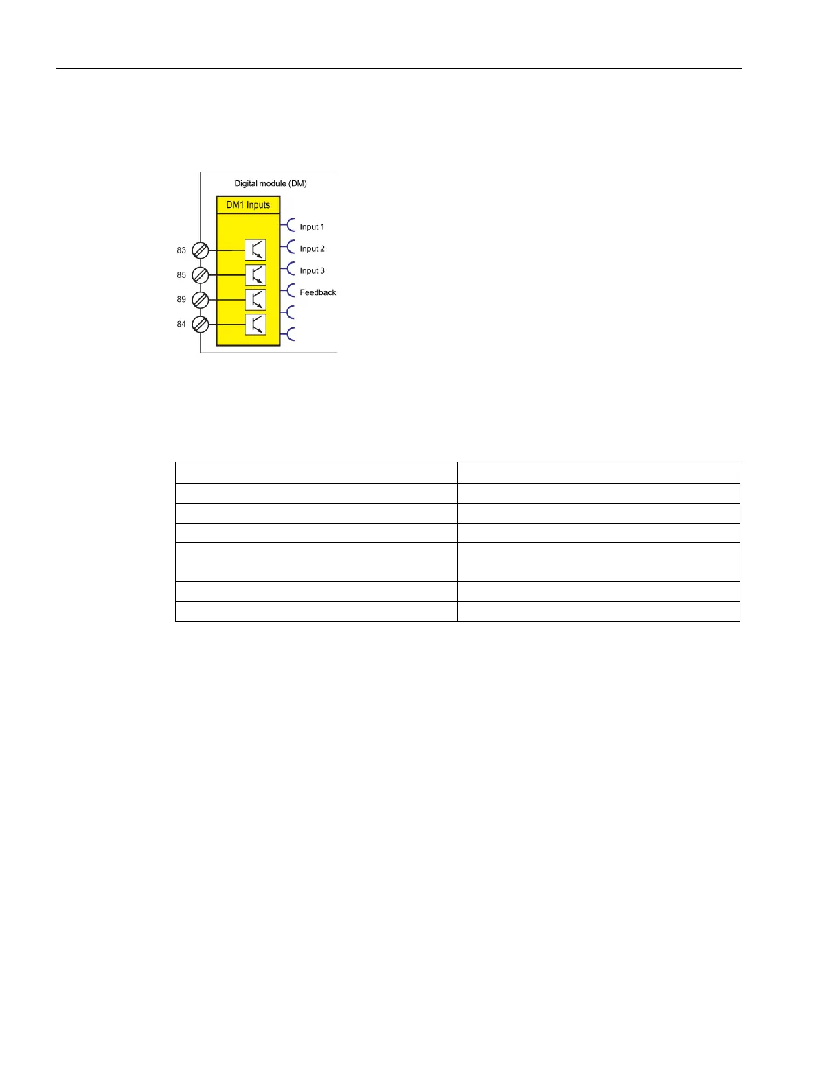
The following schematic shows the "DM1 Inputs" function block as fail-safe digital module
DM-F PROFIsafe:
Figure 4-66 The following schematic shows the "DM1 Inputs" function block as fail-safe digital
module DM-F PROFIsafe:
Table 4- 61 The following schematic shows the "DM1 Inputs" function block as fail-safe digital
module DM-F PROFIsafe
input 2 IN2 (85) state
Feedback Feedback circuit state FBC (91):
Digital modules allow the number of binary inputs and binary outputs on SIMOCODE pro V
basic unit to be increased in increments. SIMOCODE pro V can thus be extended to a
maximum of twelve binary inputs and seven binary outputs. If assigned accordingly, the input
signals can be also used to activate, for example, function blocks such as "Reset" or
"External Fault". An external fault can be, for example, the binary signal of an external speed
monitor, signaling that the nominal speed of a motor has been undershot.
Power supply to the inputs
See "Description of system components → Digital module" and "Description of system
components → Fail-safe digital modules" in the SIMOCODE pro system manual.