CU305 Control Units
7.3 Interface description
SINAMICS S110
136 Manual, 07/2015, 6SL3097-4AC10-0BP5
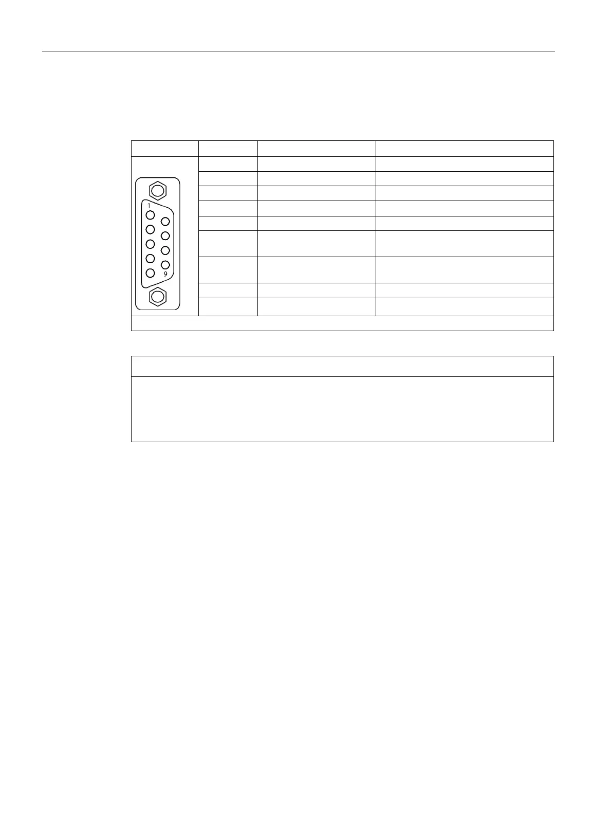
X126 PROFIBUS/USS interface
Table 7- 5 X126 PROFIBUS/USS interface
RS485 differential signal
4 1RTS_DP Request To Send
6 1P5 5 V power supply for bus terminal, exter-
7 P24_SERV 24 V for teleservice, short circuit-proof,
RS485 differential signal
9 Reserved, do not use
Destruction of the CU305 DP when a CAN cable is connected
When a CAN cable is connected to the X126 interface, the CU305 DP or other CAN bus
node can be irreparably damaged.
• Do not connect any CAN cable to the X126 interface.
Communication with USS protocol via RS485
Interface X126 can also be used for communication with USS involving up to 32 nodes. The
STARTER software is used to change the PROFIBUS factory setting to USS. For operation
as a USS interface, only terminals 3, 5, and 8 are used.
You will find information on configuration in the SINAMICS S110 Function Manual.
PROFIBUS/USS address switch
With the CU305 DP, the address switch can be used to set both PROFIBUS addresses and
USS addresses. Operation via USS is only possible if the factory setting in the STARTER of
PROFIBUS is changed to USS.
The factory setting for the address switch is 0 or 127. The address switch is located behind
the blanking plate. The blanking plate is part of the scope of supply.