SIREMOBIL Iso-C SPR2-230.061.01 Page 22 of 48 Siemens AG
System Manual Rev. 13 12.04 CS PS 24 Medical Solutions
6 - 22 Replacing boards / replacing components
Centering the camera optics to the I.I. output 6
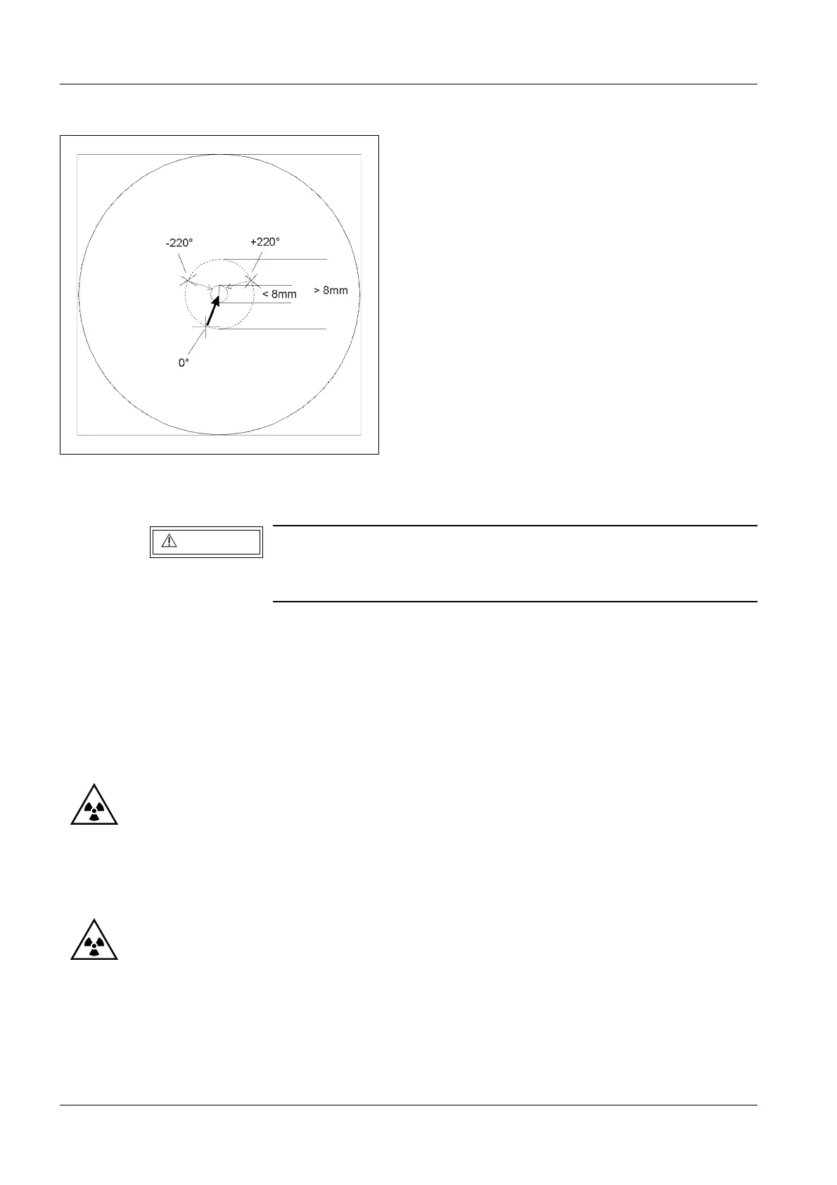
Prerequisite: The +220°, -220° and 0° positions were already marked as previously
described.
• Rotate the camera optics back to the 0° position.
• Loosen the three attachment screws of the camera optics slightly.
• Loosen both eccentric screws adjacent to the camera optics slightly .
• Move the camera optics toward the center, between both +220° and -220° markings (Re-
fer also to Fig. 9).
• Switch fluoro on briefly and evaluate the position on the monitor.
According to the ratio of the I.I. input screen diameter to the I.I. output screen diameter, a
shift of the camera optics by approximately 0.1 mm corresponds to a position shift of the
washer displayed on the monitor of more than 1.7 mm (23 cm I.I.).
• Secure the camera optics again.
• Erase the three markings on the monitor.
• Switch fluoro on briefly and mark the new 0° position.
• Rotate the camera to the -220° position.
• Mark the center on the monitor.
• Rotate the camera to the + 220° position.
• Mark the center on the monitor.
Fig. 8
X-ray radiation!
See Chapter 1, Safety Information.
Use radiation protection! Wear a lead apron.
WARNING
 Loading...


