SIREMOBIL Iso-C SPR2-230.061.01 Page 2 of 10 Siemens AG
System Manual Rev. 13 12.04 CS PS 24 Medical Solutions
7 - 2 Brakes / Movements
Measuring the orbital force required for movement 7
The attachment point for the spring scale is the end of the railing near the image intensi-
fier in sector B. The carriage must always be pulled along the C-arm with a consistent
speed.
Movement when brakes are released
¹ C-arm in vertical position, the force used to move the C-arm consistently must
not exceed 80 N.
¹ C-arm in horizontal position, the force used to move the C-arm consistently must
not exceed 90 N.
¹ When brakes are applied, the force required for movement when the C-arm is in
the vertical position is >
100 Nm.
Measuring the angular force required for movement 7
The attachment point for the measurement is the railing next to the image intensifier,
where the C-arm has an orbital position of 0° and an angulation of 0°.
¹ When the brakes are released, the force required for movement is between
20 and 30 N.
¹ When the brakes are applied, the force required for movement must exceed
100 N in order to move the C-arm.
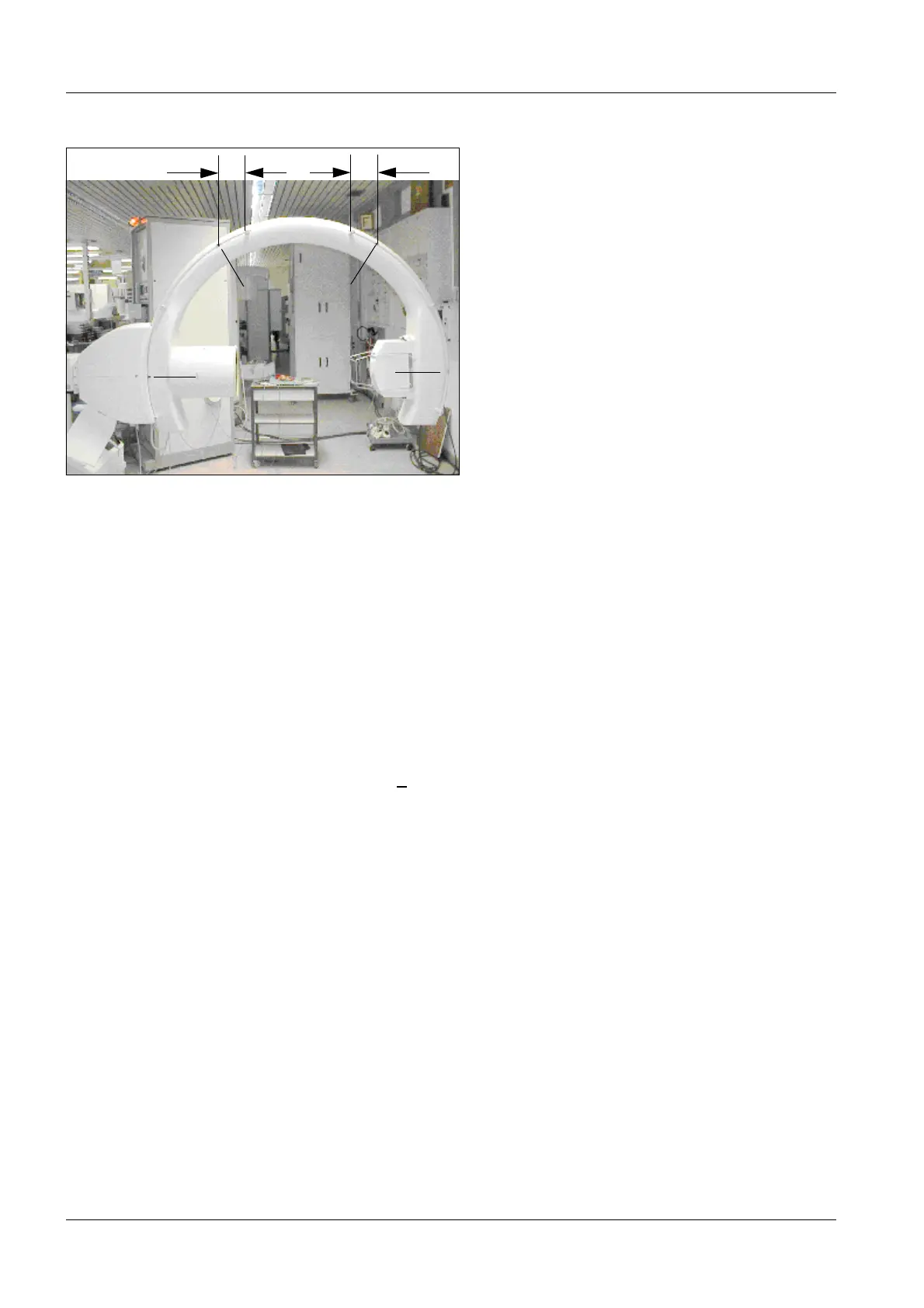
Fig. 2
Measurement A-C:Start at 90° (RBV), pull spring scale to -90° (SIREPHOS)
The C-arm opening faces downward at the start of the measurement
Measurement C-A:Start at -90° (SIREPHOS), pull spring scale to 90° (RBV)
The C-arm opening faces downward at the start of the measurement
Sector B
S
e
c
t
o
r
A
S
e
c
t
o
r
C
160
160
 Loading...


