SIREMOBIL Iso-C SPR2-230.061.01 Page 36 of 48 Siemens AG
System Manual Rev. 13 12.04 CS PS 24 Medical Solutions
6 - 36 Replacing boards / replacing components
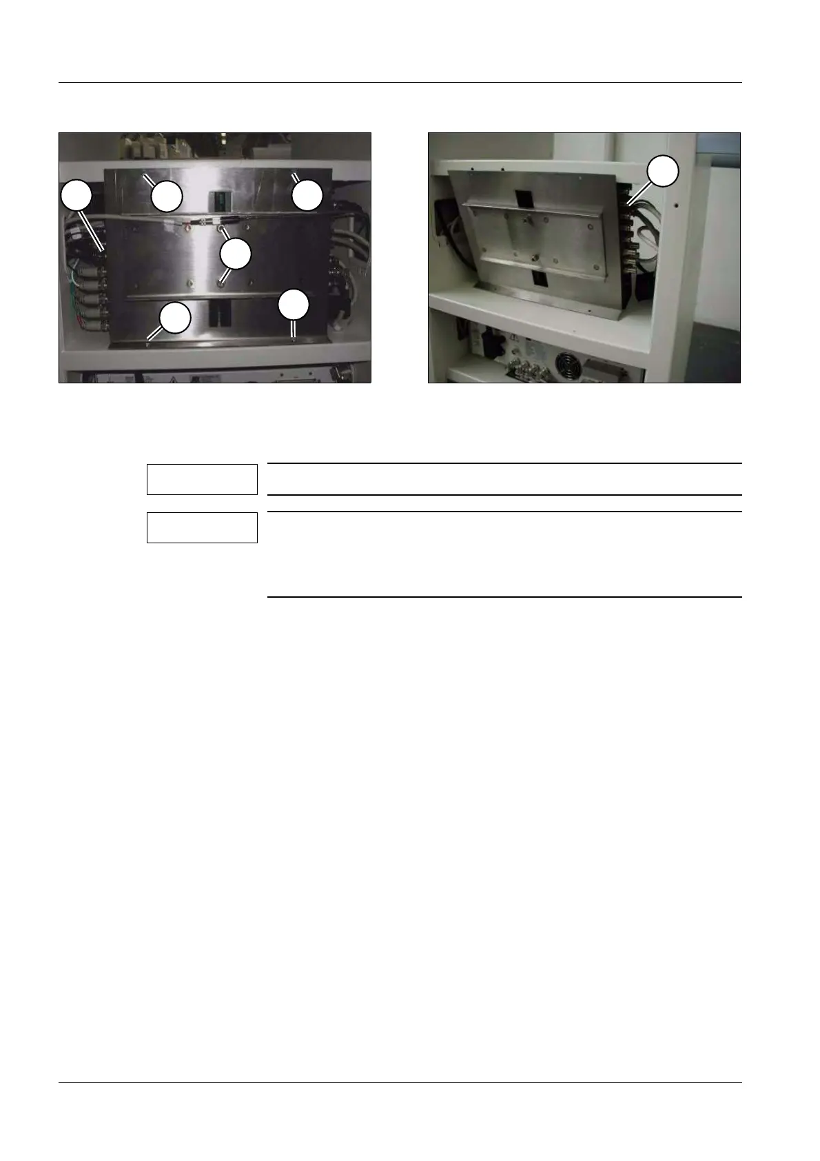
Video switcher 6
• Switch the system off.
• Loosen the four fastening screws of the securing bracket (1/Fig. 9).
• Loosen the two clamping screws, but do not unscrew them completely (2/Fig. 9).
• Tip the holding plate with the video switchers into the monitor trolley compartment
(see Fig. 10).
• Unplug the connectors of the video switcher to be replaced.
• Pull the video switcher to be replaced out of the holding plate from the side.
• Depress the green button on the video switcher.
• Push the new video switcher into the holding plate and reconnect all connectors.
• Screw the holding plate back onto the monitor trolley.
• Tighten the two clamping screws again.
• Switch the system on.
• After the system run-up, the SIMOMED HM Monitor (reference monitor) should display
the MEMOSKOP reference image. If the run-up process of the 3D reconstruction PC or
the syngo interface appears, the green button of video switcher 1 is in the wrong position
and needs to be switched over. (3/Fig. 9) points to video switcher 1.
• Perform the IQ quick test.
Fig. 9 Fig. 10
Only applies to SIREMOBIL Iso-C 3D.
Video switcher 1 (3/Fig. 9) is used to switch the video signal
between the MEMOSKOP and the 3D reconstruction PC.
Video switcher 2 (1/Fig. 10) is used to route the video signal to the
video printer.
1
3
1
1
2
1
1
NOTE
NOTE
 Loading...


