9 – 13
Overcurrent protection settings
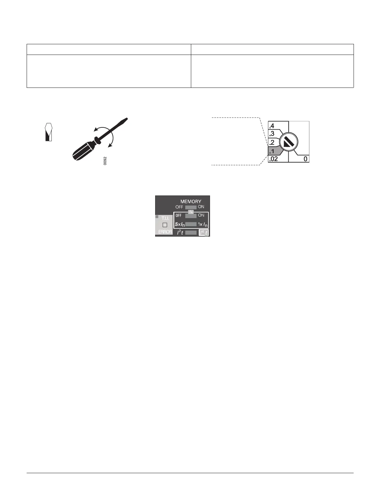
The parameters for the basic functions are adjusted with rotary cod-
ing switches.
Various additional functions are adjusted with slide switches.
The settings for the additional function "load monitoring" can be
ad
justed via:
- the alphanumeric display q (page 9-29)
- the BDA q (page 9-119)
- the PROFIBUS-DP
- the MODBUS
These settings can only be adjusted if the trip unit is activated, i.e. it
m
ust be connected to an external 24 V DC voltage supply (UL
Listed Class 2).
Protective functions
q Overload protection – L-tripping (page 9-22)
q Short-time-delay short-circuit tripping –
S-tripping (page 9-22)
q Instantaneous short-circuit tripping –
I-tripping (page 9-23)
q Ground-fault tripping – G-tripping (page 9-24)
q Neutral conductor protection - N-tripping (page 9-24)
q Load monitoring (load shed/load restore) (page 9-25)
q Leading signal for "L-tripping" (page 9-25)
q Switching on/off thermal memory (page 9-25)
q Ground-fault protection modules (page 9-68)
Einstellen des Überstromschutzes
Die Einstellung der Parameter für die Grundfunktionen erfolgt mit
Drehkodierschaltern.
Verschiedene Zusatzfunktionen werden mit Schiebeschaltern ein-
gestellt.
Die Einstellungen für die Zusatzfunktion „Lastüberwachung“ können
erf
olgen über:
- das alphanumerische Display q (Seite 9-29)
- den BDA q (Seite 9-119)
- den PROFIBUS-DP
- den MODBUS
Diese Einstellungen können nur vorgenommen werden, wenn der
Überst
romauslöser aktiviert ist, d. h. eine externe Spannungsver-
sorgung 24 V DC (Klasse 2) angeschlossen ist.
Schutzfunktionen
q Überlastschutz – L-Auslösung (Seite 9-22)
q Kurzverzögerte Kurzschlussauslösung –
S-Auslösung
(Seite 9-22)
q Unverzögerte Kurzschlussauslösung –
I-Auslösung (Seite 9-23)
q Erdschlussauslösung – G-Auslösung (Seite 9-24)
q Neutralleiterschutz – N-Auslösung (Seite 9-24)
q Lastüberwachung („Lastaufnahme/
Lastabwurf“) (Seite 9-25)
q Voreilende Meldung "L-Auslösung" (Seite 9-25)
q Thermisches Gedächtnis ein-/ausschaltbar (Seite 9-25)
q Erdschlussschutzmodule (Seite 9-68)
VORSICHT CAUTION
Parametereinstellungen grundsätzlich nur vornehmen, wenn
der Leistungsschalter ausgeschaltet ist.
Eine Veränderung der Parameter bei eingeschaltetem Lei-
stungsschalter kann zu ungewolltem Auslösen des Leistungs-
schalters führen.
Adjust parameters only when the circuit breaker is in the
OPEN position.
If the parameters are modified when the circuit breaker is
CLOSED
, the circuit breaker may trip unintentionally.
The value 0.1 is set if the
rotary switch is positioned in this zone
Der Wert 0,1 ist eingestellt,
wenn der Drehschalter
3 x 0.5
1/8“
in diesem Drehwinkelbereich steht

 Loading...


