9 – 82
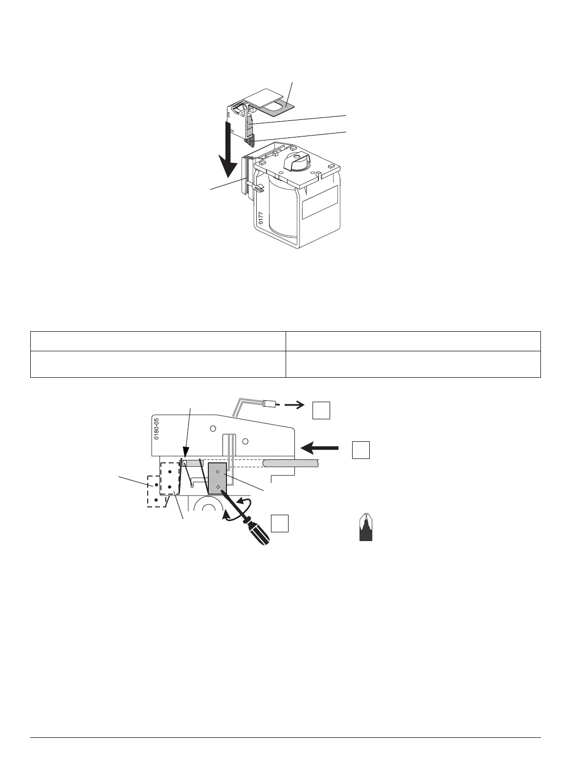
Meldeschalter am Hilfsauslöser anbringen
(1) Wippe
(2) Meldeschalter
(3) Führung
(4) Nut
Meldeschalter am Schutzmodul montieren
BSS-Modul anschließen
Der erste c-Anschluss führt an die Messerleiste X8. Der
zweite c-Anschluss erfolgt je nach Ausstattung des Lei-
stungsschalters.
VORSICHT CAUTION
Selbstschneidende Schrauben vorsichtig anziehen. Die Mel-
deschalter dürfen sich bei der Montage nicht verformen.
Tighten self-tapping screws carefully. The signaling switches
must not be deformed during installation.
(1)
(2)
(3)
(4)
1. Hilfsauslöser : Meldeschalter S 42
2. Hilfsauslöser : Meldeschalter S 43
1st shunt trip: signaling switch S 42
UVR / 2nd shunt trip: signaling switch S 43
spring / Feder
S45
S24
S13
(Rear side
Rückseite)
2
3
Fitting signaling switch on the Shunt Trip / UVR
(1) See-saw
(2) Signaling switch
(3) Guide
(4) Groove
Fitting signaling switch on the protection module
Connecting BSS module
The first c connection leads to the receptacle X8. The
second c connection is performed according to the cir-
cuit breaker equipment.
Pz 0
BSS module
BSS-Modul
1

 Loading...


