9 – 107
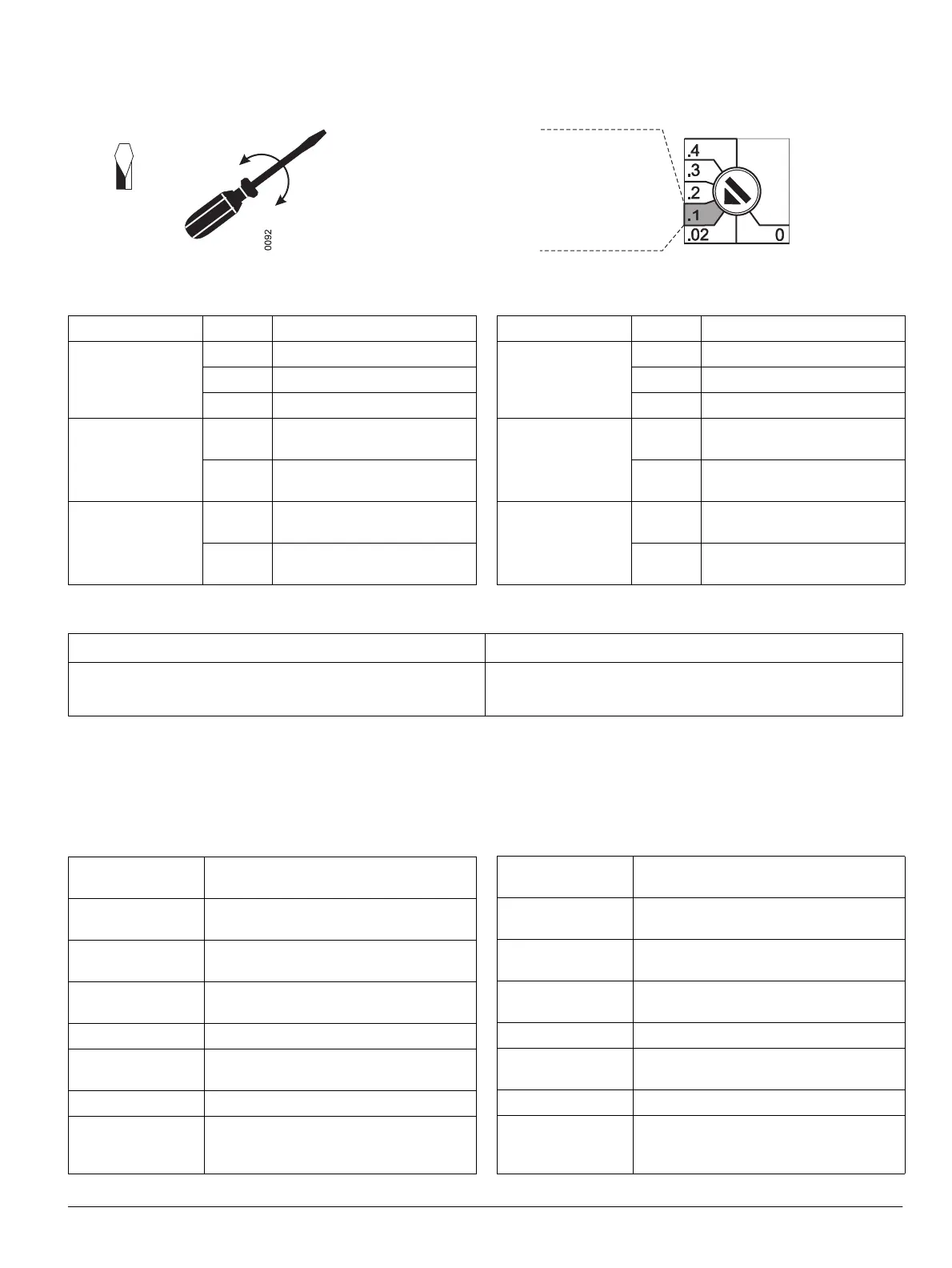
Setting principle
Indicators
Module test
The perfect operation of the c modules can be verified in
the test mode. The test mode is started by pressing the "TEST" but-
ton once. All outputs and the associated LED's are switched off. The
co
lor of the DEVICE LED changes from green to yellow.
Testing inputs and outputs
LED Indication Significance
DEVICE
green Module in operation
yellow Module in test mode
red Module faulty
c
green
Connection to c
available
off
No connection to c
All other LED‘s
yellow
Option set or signal available
off
Option not set or no signal
available
Pressing the "TEST"
But
ton
Reaction
Twice quickly - LED 1 on
- Input/output 1 on
After a pause,
twice quickly
- LED 1 and input/output 1 off, LED 2 on
- Input/output 2 on
After a pause,
twice quickly
- LED 2 and input/output 2 off, LED 3 on
- Input/output 3 on
... ...
After a pause,
twice quickly
- LED 5 and input/output 1 off, LED 6 on
- Input/output 6 on
After a pause, once Input/output 6 on
Once Test mode starts again, all inputs/outputs and
the associated LED
's are off
Einstellprinzip
Anzeigen
Modultest
Die korrekte Funktion der c-Module kann im Test-Modus
überprüft werden. Einmaliges Betätigen der Taste „TEST“ startet
den Test-Modus. Alle Ausgänge und die dazu gehörenden LEDs
werden ausgeschaltet. Die Farbe der DEVICE-LED wechselt von
grün auf gelb.
Prüfen der Ein- und Ausgänge
LED Anzeige Bedeutung
DEVICE
grün Modul in Betrieb
gelb Modul im Testmodus
rot Modul gestört
c
grün
Verbindung zum
c
besteht
aus
keine Verbindung zum
c
alle anderen LED
gelb
Option eingestellt bzw. Meldung
v
orhanden
aus
Option nicht eingestellt bzw. keine
Meldung v
orhanden
VORSICHT CAUTION
Um Fehlfunktionen des Leistungsschalters oder einer seiner
Komponenten zu vermeiden, den Test nur vor einer Inbetrieb-
nahme durchführen.
To avoid malfunctions of the circuit-breaker or one of its com-
ponents, perform the test before commissioning only.
Betätigen der Taste
„TEST“
Wirkung
2x kurz nacheinander - LED 1 ein
- Ein- / Ausgang 1 ein
Nach Pause,
2x kurz nacheinander
- LED 1 und Ein- / Ausgang 1 aus, LED 2 ein
- Ein- / Ausgang 2 ein
Nach Pause,
2x kurz nacheinander
- LED 2 und Ein- / Ausgang 2 aus, LED 3 ein
- Ein- / Ausgang 3 ein
... ...
Nach Pause,
2x kurz nacheinander
- LED 5 und Ein- / Ausgang 5 aus, LED 6 ein
- Ein- / Ausgang 6 ein
Nach Pause, 1x Ein- / Ausgang 6 aus, alle LEDs ein
1x Test-Modus beginnt von vorn, alle Ein- / Aus-
gänge und die dazu gehörenden LEDs sind
aus
The value 0.1 is set if the
rotary switch is positioned in this zone
Der Wert 0,1 ist eingestellt,
wenn der Drehschalter
3 x 0.5
1/8“
in diesem Drehwinkelbereich steht

 Loading...


