19 – 10
Funktionsprobe
Anschließend:
- Bedienpult und ggf. rechte seitliche Abdeckung wieder
anba
uen q (Seite 24-4)
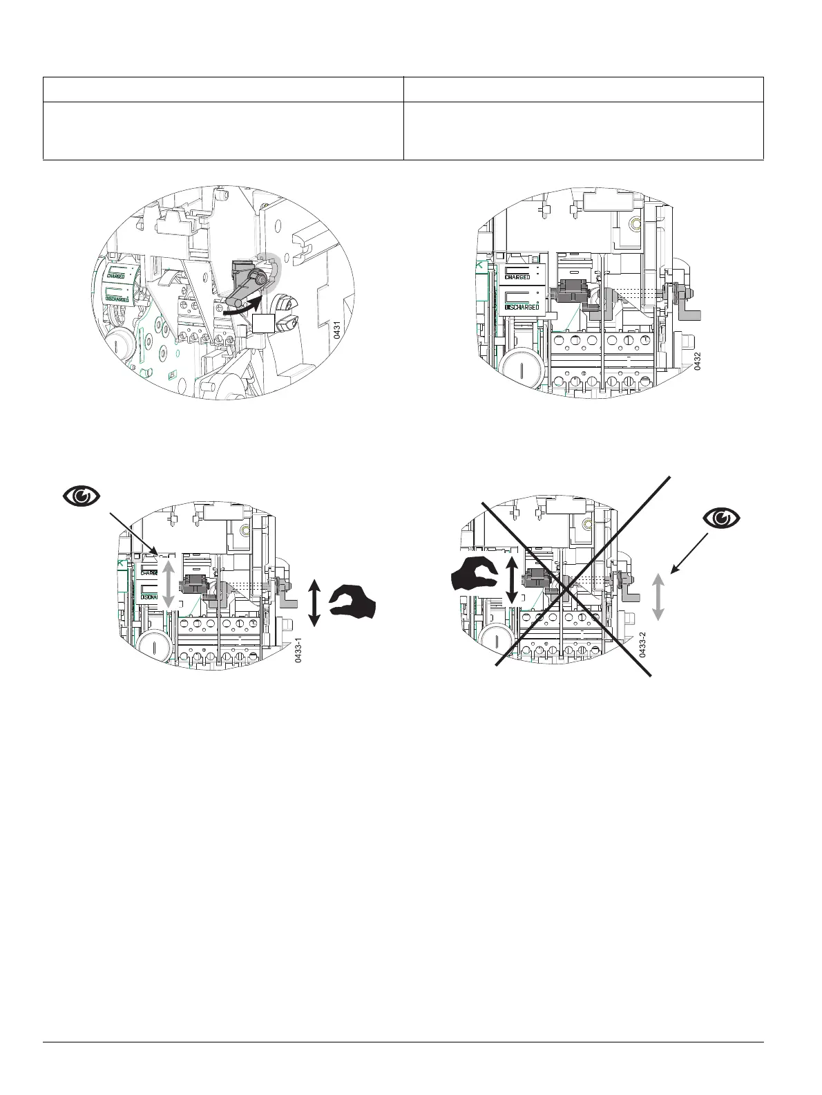
HINWEIS NOTICE
Im Arbeitsschritt 9 muss die Zwischenwelle in eine Bohrung im
Schalterinneren einrasten.
Erst dann lässt sich im Arbeitsschritt 10 di
e Halterung der Zwi-
schenwelle in die Führung der Seitenwand eingesetzen.
In step 9, the intermediate shaft must engage in a hole inside
th
e circuit breaker.
Only then it will be possible - in step 10 - to fit the support for the
in
termediate shaft into the guide of the side wall.
10
Function check
Then:
- Replace front panel and side cover on the right, if it was
remo
ved q (page 24-4)

 Loading...


