25 – 9
WL Circuit Breaker
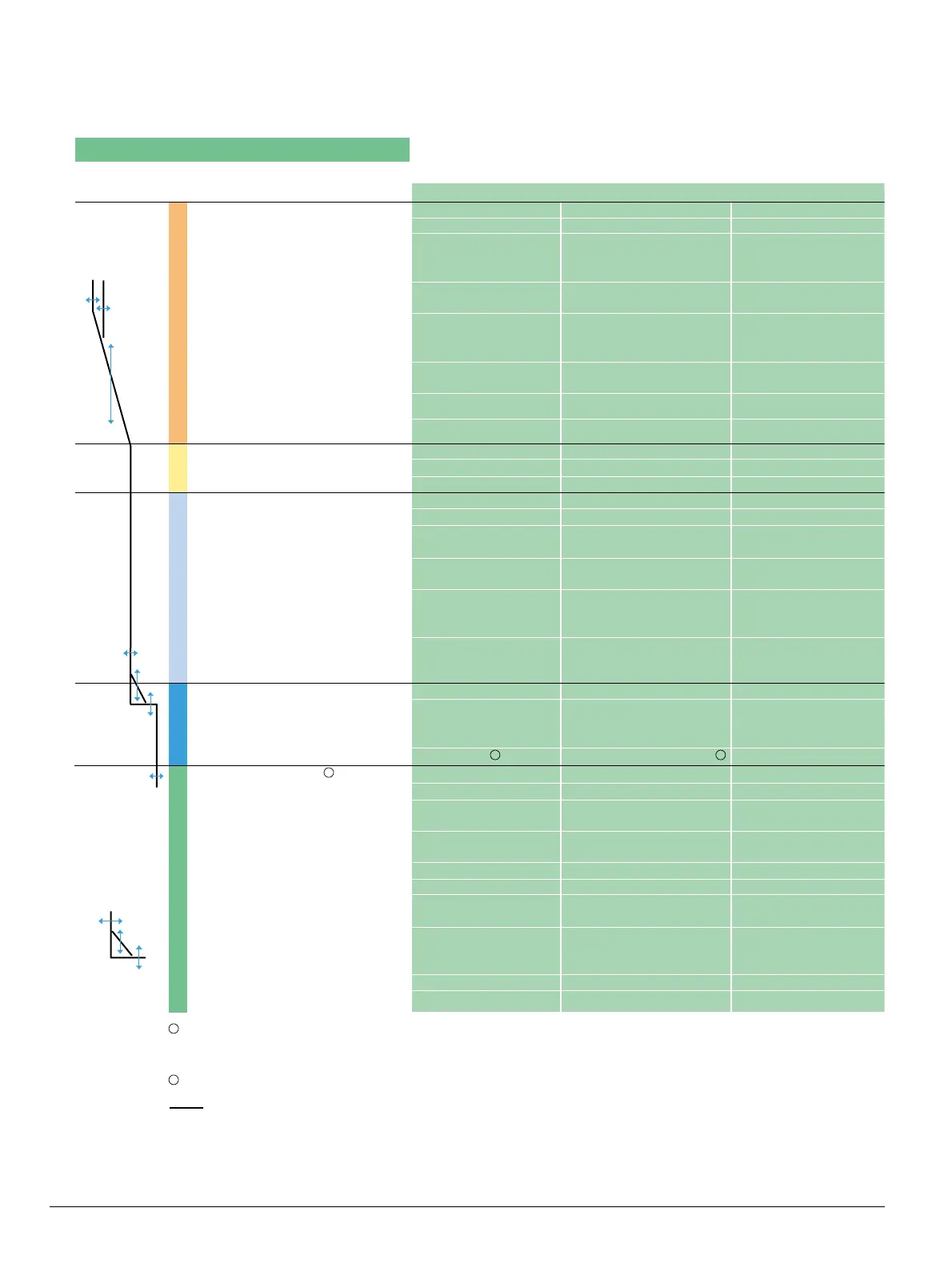
Function Overview of the Electronic Trip Units
Basic Functions ETU748 ETU755 ETU776
Long-time overcurrent protection ✔✔ ✔
Function can be switched ON/OFF – – –
Setting range
I
R
=
I
n
x … 0.4, 0.45, 0.5, 0.55, 0.4 … 1 (step: 1A) 0.4 … 1 (step: 1A)
0.6, 0.65, 0.7, 0.8,
0.9, 1
Switch-selectable overload protection
(
I
2
t or
I
4
t dependent function) ✔✔(via communications) ✔
Setting range of time delay class
t
R
at
I
2
t
(seconds) 2, 3.5, 5.5, 8, 10, 2 … 30 (step: 0.1s) 2 … 30 (step: 0.1s)
14, 17, 21, 25, 30
Setting range of time delay
t
R
at
I
4
t
(seconds) 1, 2, 3, 4, 5 1 … 5 (step: 0.1s) 1 … 5 (step: 0.1s)
Thermal memory ✔
(via slide switch) ✔
(on/off via communications)
✔
(on/off via key pad
or communications)
Phase loss sensitivity at
t
sd
=20ms (M) ✔
(on/off via communications)
✔
(on/off via key pad
or communications)
N-conductor protection – ✔✔
Function can be switched ON/OFF – ✔ (via slide switch) ✔ (via slide switch)
N-conductor setting range
I
N
=
I
n
x …
– 1 0.5 … 1
Short-time delayed overcurrent protection ✔✔ ✔
Function can be switched ON/OFF ✔
(via rotary switch) ✔ (via communications) ✔
(via key pad or communications)
Setting range
I
sd
=
I
n
x … 1.25, 1.5, 2, 2.5, 1.25 … 0.8 x I
cw
= max 1.25 … 0.8 x I
cw
= max
3, 4, 6, 8, 10, 12 (step: 10A) (step: 10A)
Setting range of time delay
t
sd
,fixed
(seconds) M, 0.1, 0.2, 0.3, 0.4
M, 0.08 … 0.4, OFF (step: 0.001s) M, 0.08 … 0.4, OFF (step: 0.001s)
Switch-selectable short -time delay
short-circuit protection
(
I
2
t
dependent function) ✔ (via rotary switch) ✔ (via communications) ✔
(via key pad or communications)
Setting range of time delay
t
sd
at
I
2
t
(seconds) 0.1, 0.2, 0.3, 0.4 0.1 … 0.4 (step: 0.001s) 0.1 … 0.4 (step: 0.001s)
Zone Selective Interlocking (ZSI) function per CubicleBUS module per CubicleBUS module per CubicleBUS module
Instantaneous overcurrent protection ✔✔ ✔
Function can be switched ON/OFF,
Extended Instantaneous Protection
is enabled when OFF – ✔
(via communications) ✔
(via key pad or communications)
Setting range
I
i
=
I
n
x … –
I
i
=
I
cw
= EIP
1.5 x
I
n
… 0.8 x
I
cs
= max, OFF=
I
cw
=EIP 1.5 x
I
n
… 0.8 x
I
cs
= max, OFF=
I
cw
=EI
Ground fault protection O (field installable module) O (field installable module) O (field installable module)
Trip and alarm function ✔✔
(via communications) ✔
(via key pad or communications)
Detection of the ground fault current
by residual summing method ✔✔ ✔
Detection of the ground fault current
by direct summing method ✔✔ ✔
Setting range of the
I
g
for trip A, B, C, D, E A … E (step: 1A) A … E (step: 1A)
Setting range of the
I
g
for alarm A, B, C, D, E A … E (step: 1A)- A … E (step: 1A)
Setting range of the time delay
t
g
(seconds) 0.1, 0.2, 0.3, 0.4, 0.5 0.1 … 0.5 (step: 0.001s) 0.1 … 0.5 (step: 0.001s)
Switch-selectable
ground fault protection
(
I
2
t
/ fixed) ✔✔ ✔
Setting range time delay
t
g
at
I
2
t
0.1, 0.2, 0.3, 0.4, 0.5 0.1 … 0.5 (step: 0.001s) 0.1 … 0.5 (step: 0.001s)
ZSI ground function per CubicleBUS module per CubicleBUS module per CubicleBUS module
✔ available
– not available
O optional
L
N
S
I
G
Extended Instantaneous Protection (EIP) allows the WL breaker to be applied at the withstand rating of
the breaker with minus 0% tolerance; that means no instantaneous override whatsoever. EIP further
enables the circuit breaker to be applied up to the full instantaneous rating of the breaker on systems
where the available fault current exceeds the withstand rating.
Ground Fault Module cannot be removed after installation.
1
2
Notes:
M = Motor protection setting (20 ms)
Communications = Setting the parameters of the trip unit
via the Breaker Data Adapter, MODBUS, or PROFIBUS
Key pad = Direct input at the trip unit
I
n
2
1
1

 Loading...


