5 – 31
5.6.1 Nachrüsten
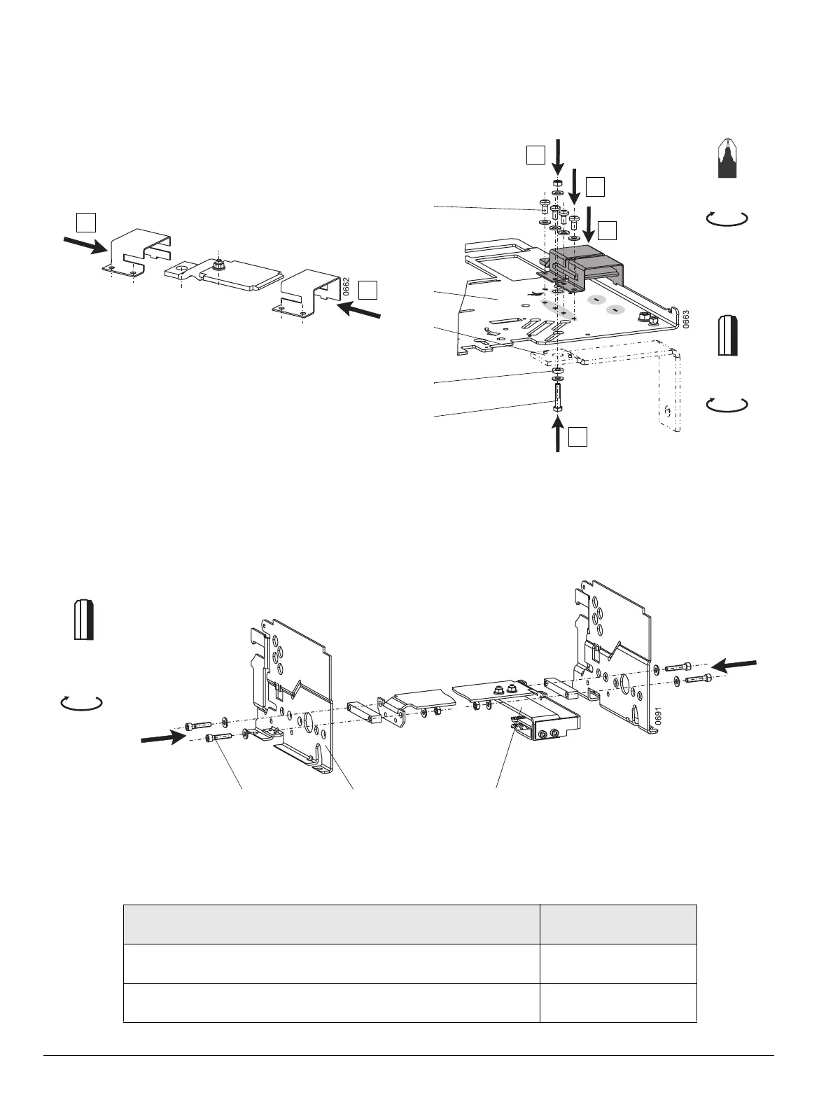
Anbau des Kontaktmoduls am Einschubrahmen
(1) Zylinderschraube M6 mit Scheiben und Mutter
(2) Kupferscheibe
(3) Erdungswinkel (Kundenbeistellung)
(4) Bodenblech Einschubrahmen
(5) 4x selbstschneidende Schraube M4 mit Scheibe
Kontaktmodul am Einschubschalter anbauen
(1) 4x Zylinderkopfschraube M6 mit Scheiben und Mutter
(2) Schalterfuß
(3) Kontaktmodul
5.6.2 Bestell-Nummern
Catalog No.
Bestell-Nr.
Additional grounding between the breaker and the guide frame, for FS II
Kontaktmodul für Einschubrahmen BG II
WLEF2
Additional grounding between the breaker and the guide frame, for FS III
Kontaktmodul für Einschubrahmen BG III
WLEF3
1
1
(3)
(4)
(1)
(5)
(2)
Gr. / Size
5
2
3
5
4
PZ 2
3,2 Nm
8 Nm
28 lb-in
71 lb-in
Gr. / Size
5
8 Nm
(1) (2) (3)
71 lb-in
5.6.1 Field installing
Installing ground pad on the guide frame
(1) M6 cheese-head screw with nuts and washers (hex key)
(2) Copper plate
(3) Ground strap (to be provided by customer)
(4) Base plate of guide frame
(5) 4x self-tapping M4 screws with washer ( pozidrive)
Attaching ground pad on the draw-out circuit breaker
(1) 4x M6 cheese-head screws
(2) Foot of draw-out circuit breaker
(3) Ground pad
5.6.2 Catalog numbers

 Loading...


