Keyboard not working
(partially or completely)
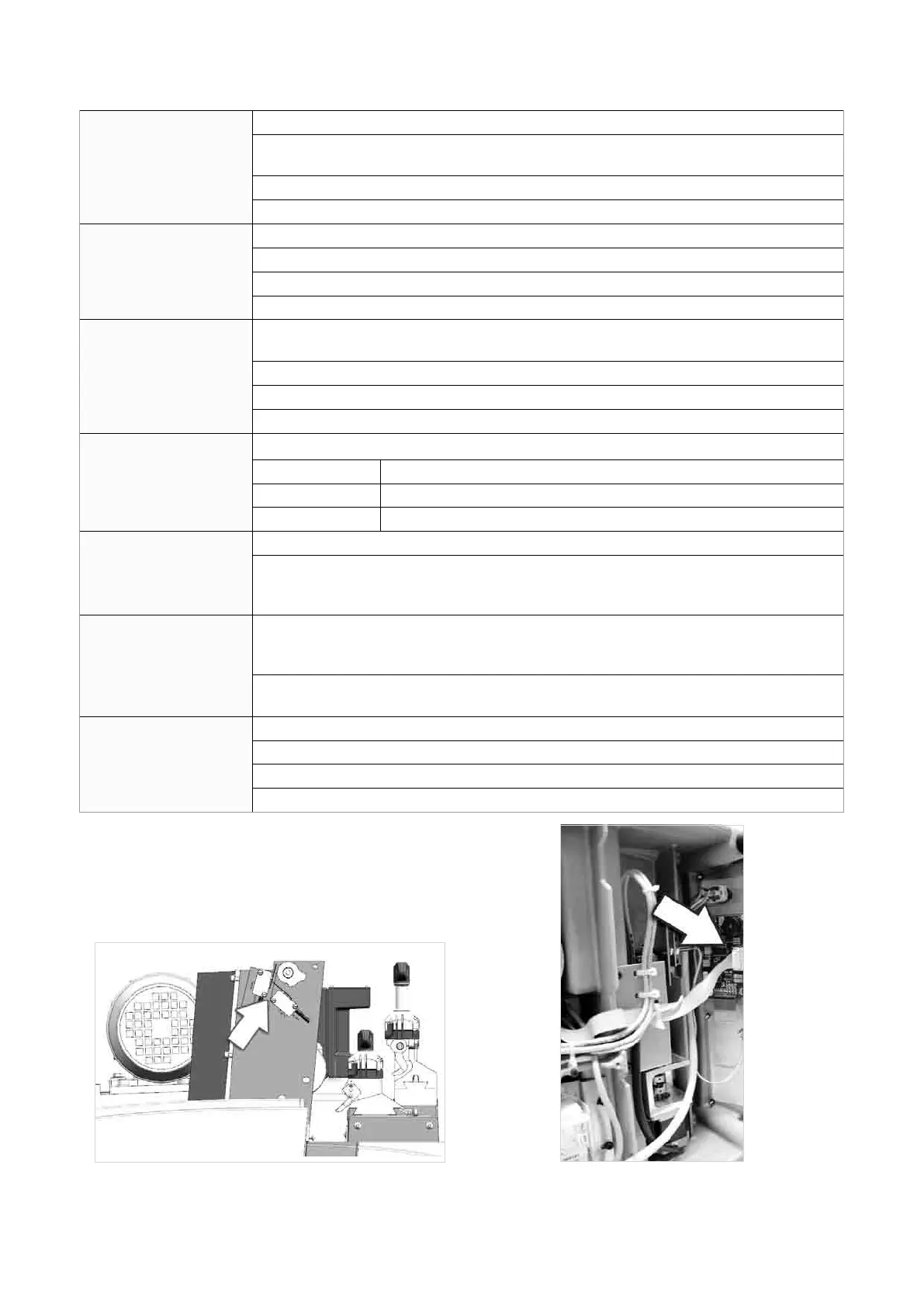
a) the keyboard connector is not properly connected to the interface board (Fig. 73)
b) the wiring between the keyboard/display unit and electronic control board is not prop-
erly attached to the relative connectors
c) defective keyboard
d) defective electronic control board
Optical reader not wor-
king
a) glass lent on the optical reader is dirty
b) wiring between optical reader and the electronic control board is not seeded properly
c) defective optical reader
d) defective electronic control board
Key-cutting machine fails
to communicate with
computer
a) wiring between 9-pin serial port and electronic circuit board not seeded properly or
disconnected
b) serial cable between key-cutting machine and computer is faulty
c) computer serial port is not functional
d) defective electronic control board
The display shows the
message: “TEMPERA-
TURE ALARM - turn the
machine off”
Check that the fan on the back of the key-cutting machine is working:
Not working: a) fan fault
b) electronic control board faulty
Working: electronic control board fau
The display shows the
message: “I/O POWER
ALARM check fuse F4”
a) fuse F4 on the electronic control board faulty
b)shortcircuitoninletsoroutlets.Tondwhichinletoroutletiscausingtheerrormes-
sage, disconnect the J4-5-7-8-12-14-15-20 connectors one at a time and check each
time whether the alarm disappears
The display shows the
message: “DIGITAL
OUTLET
PROTECTION ALARM -
turn the machine off”
a)shortcircuitontheoutlets.Tondwhichoutletiscausingtheerrormessage,discon-
nect the J4-5 connectors one at a time and check each time whether the alarm disap-
pears
b) internal fault on the electronic control board
The display shows the
message: “CUTTER
MOTOR ALARM -
check fuse F1”
a) fuse F1 on the electronic control board faulty
b) cutter microswitch on protective cover triggered or disconnected (Fig. 72)
c) cutter motor wiring disconnected
d) internal fault on the electronic control board
Fig. 72 Fig. 73
Operating Manual UC199
Copyright Silca 2012
71