5-9
Connecting 4010ES basic components, continued
Connecting the
MSS
Follow the steps below:
1. Connect the MSS to the MSS (Block C) connector on the Top Bay PDI.
2. Attach the MSS to the back box using metal screws and standoffs.
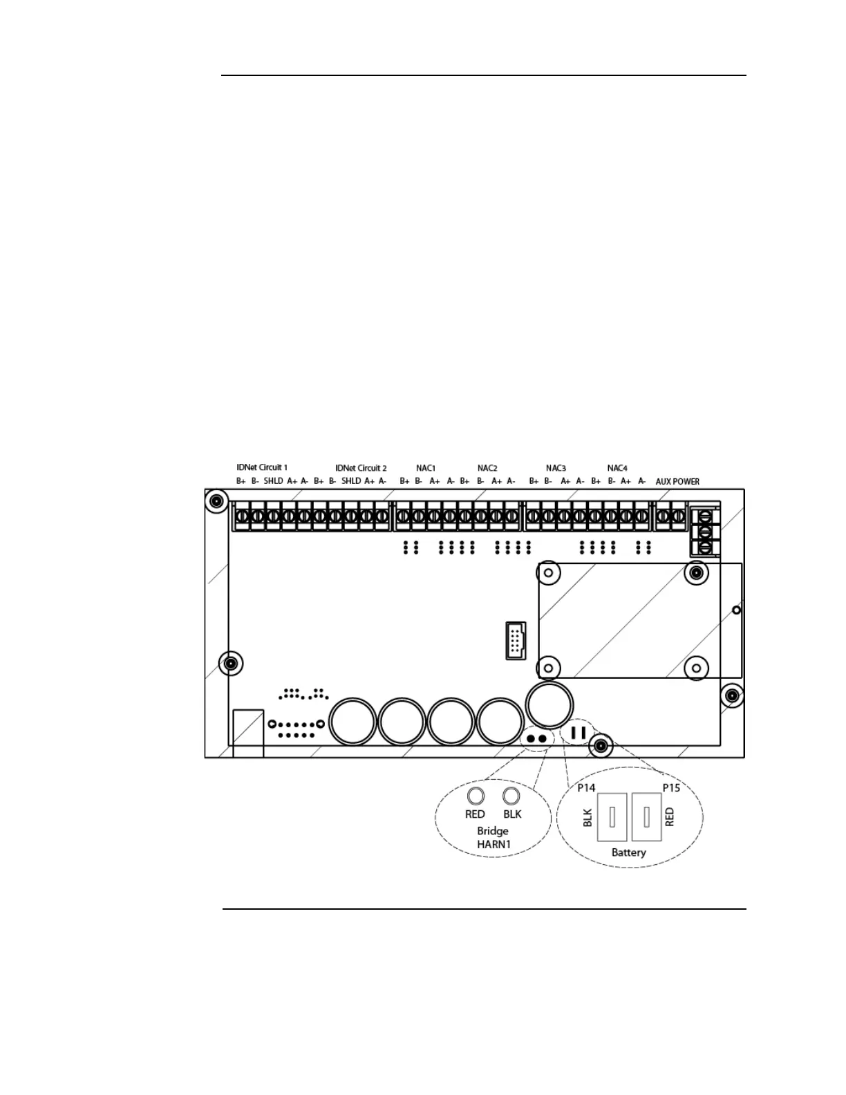
3. Connect the rectifier to the Bridge HARN1 connectors on the MSS (Figure 5-9). The red
wire connects to the tab labeled “+” on the bridge. The black wire connects to the tab labeled
“-” on the rectifier. See Figure 5-8 for the location of the rectifier.
4. Connect the backup batteries to the Battery connectors on the MSS. The red wire connects
to the tab labeled "RED" on the MSS, the black wire connects to the “BLK” tab. The backup
batteries must be wired in series such that you have 24 V. Use the white wire provided to
bridge the batteries together. The batteries can be placed on the bottom of the 4010ES back
box.
Notes: 1. A fused harness is required to connect the backup batteries. That harness is shipped with the
panel. The mating spade lug on the battery should be 0.250 inch x 0.032 inches. If another size is
needed, you will need to replace the battery terminal connectors on the supplied battery harness.
2. One-bay system back boxes support up to 33 Ah batteries. Two-bay system back boxes support
up to 50 Ah batteries. If 50 Ah batteries are used, you must also order the 4100-0650 Battery
Shelf.
3. To minimize the power losses due to wiring from the battery box to the 4010ES, use at least a
12 AWG wire and keep the battery box at the minimum distance possible from the 4010ES.
Figure 5-9. MSS Bridge HARN1 connector