Installation
20169223D 5-15
Adjustments
Normally no adjustment is necessary in the Distribution Unit.
However, if the unit includes the Dual Analogue Board or the
Thruster Interface Board, these boards must be set up during
installation in accordance with the set up procedure on page 5-50.
1
2
3
4
31
42
J/P2
ANALOG I/P
ANALOG I/P GND.
TB4
ANALOGUE
INTERCONNECTION PCB.
AP9 MK3
MAIN CONTROL
UNIT
ANALOGUE
STEERING
UNIT
S11 MUST BE SET TO
POSITION "0"
TB21
1
2
3
4
VOLT O/P
CURRENT O/P RETURN
CURRENT O/P
VOLT O/P COMMON
1
2
3
4
VOLT O/P
CURRENT O/P RETURN
CURRENT O/P
VOLT O/P COMMON
TB22
DUAL ANALOGUE BOARD
J1
J2
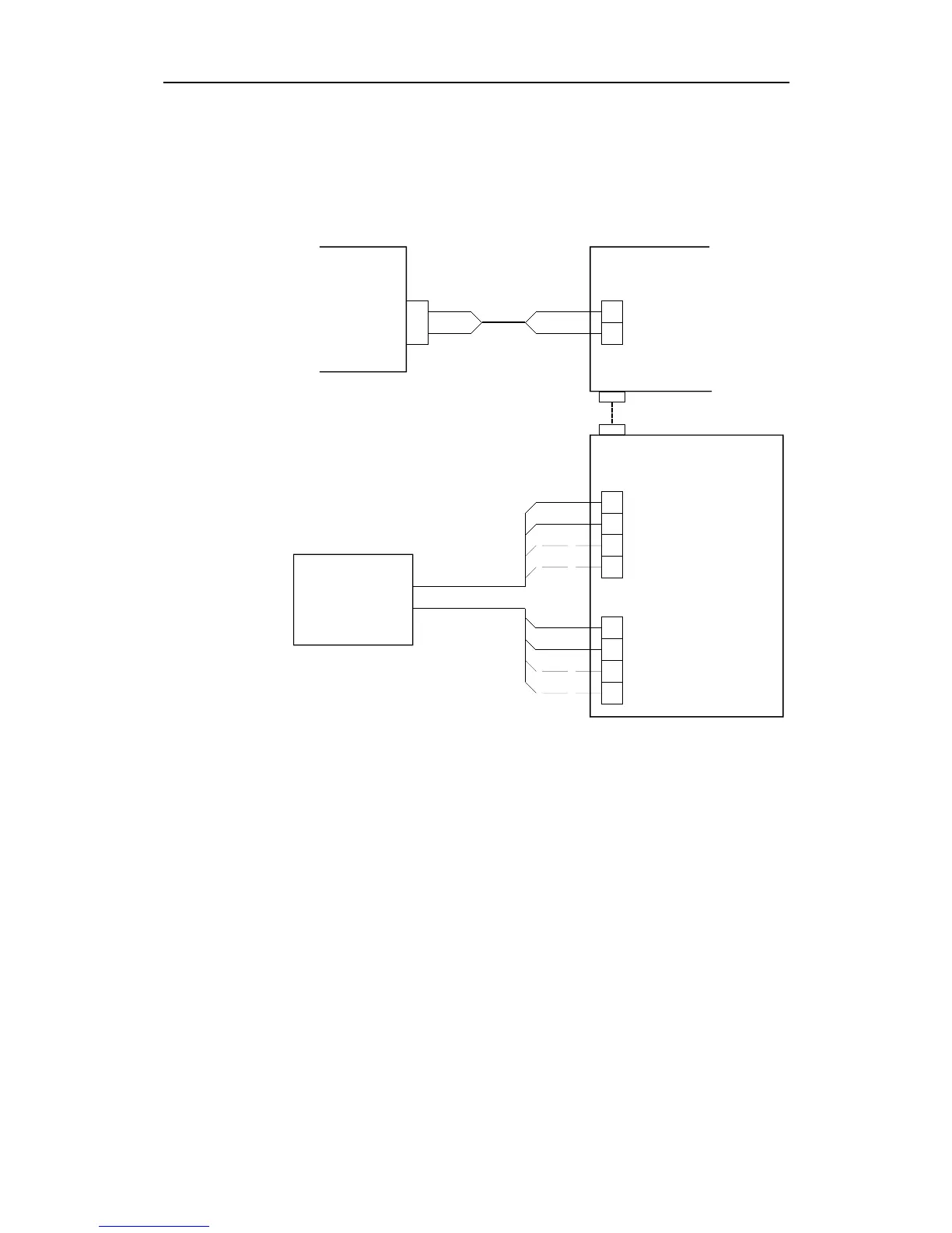
J2 of the Dual Analogue Board
is plugged directly onto J1 of
the Analogue Interconnection Board
Fig. 5-17
AP9 MK3 / D93 (Dual Analogue PCB) Interconnection
5.6 RF14XU Rudder Feedback Unit
Mechanical mounting
Before installation check that the alignment mark on the mounting
plate agrees with the mark on the shaft. Bring the rudder to Midships
position. The feedback unit should be mounted on a plane surface
and secured by bolts through the three holes in the mounting plate. It
should be linked to the rudder in accordance with Fig. 5-18. It is
important that the linkage is linear, i.e. the A-a and D-d are pairs of
equal length. This will give a ratio 1:1 between the rudder angle and
that of the feedback unit shaft. Final adjustment is made by loosen
the fixing screws for the potentiometer, and carefully turn the
potentiometer for correct positioning.