Robertson AP9 MK3 Autopilot
1-6 20169223D
1.7 Combinations of Heading Sensors
Ref. Fig. 1-5.
The AP9 MK3 Control Unit is designed to accept several types of
heading sensors. The sensors can be divided in three groups:
1. Gyro Compass
2. Fluxgate Compass (Recommended as monitor compass only)
3. Magnetic Compass (Recommended as monitor compass only)
GYRO COMPASS
To interface to SYNCHRO, GYRO EXCITED, A/P EXCITED or STEP
type gyro, the AP9 MK3 Control Unit must be equipped with the
Gyro Interface Board P/N 20168316.
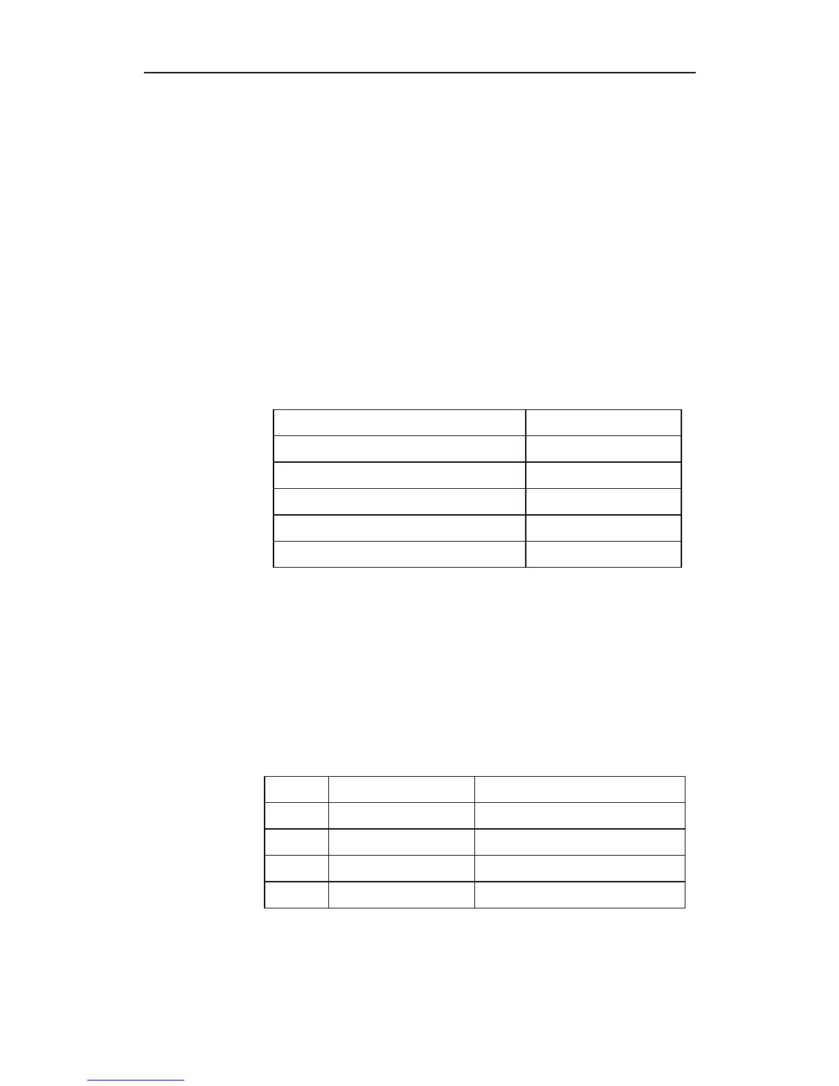
Signal type Optional hardware
Synchro 11,8V l-l 400Hz Gyro Interface PCB
Synchro 20-115V l-l 50-60Hz, 400Hz Gyro Interface PCB
Step 6 step/degree Gyro Interface PCB
Sin/cos Not required
Serial Not required
Note ! Two SYNCHRO or two STEP signals can not be connected at the same
time. When using two gyrocompasses, one gyro must provide SYNCHRO
signal and the other gyro must provide STEP signal.
When using gyro with serial signal, no Gyro Interface Board is
required.
Notice that dual station system communication can not be made
when UART or NMEA serial line is used.
The Robertson RGC gyros can be connected according to the following
table:
Direct connection RGC Interface connection
RGC10 Synchro Serial, sin/cos, 6 step/degree
RGC11 RS422 Tokimec spes. Serial, sin/cos, 6 step/degree
RGC50 Synchro Serial, sin/cos, 6 step/degree
RGC12 Serial Serial, sin/cos, 6 step/degree
For details of gyro selection see page 5-58.