Robertson AP9 MK3 Autopilot
3-12 20169223D
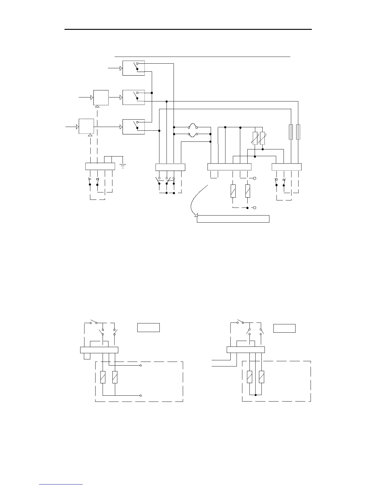
CONNECTION OF LIMIT SWITCHES AND SOLENOIDS
SEE SEPARATE DETAIL ALT. I/II
1 2 3 41 2 3 4
1 2 3 4 5 6
SAFE RELAY
IC5
IC2
IC3
TB12 TB15 TB14 TB16
NFU
LIMIT SWITCHES
(NO LOAD)
IC4-A
IC4-B
STBD
CMD.
PORT
CMD.
LIMIT SWITCHES
(SOL. LOAD)
P
S
S4
S6
S5
S7
PWR
F1 F2
1 2 3 4
Fig. 3-12
Solid state PCB - connection of limit switches
When the RF14XU limit switches are connected to the TB12, only
control signals are switched. When the limit switches are connected
to TB16, the solenoid load (current) is switched. It is recommended
not to use the TB16 connections if the load exceeds appr. 30W. If so,
TB16 no. 1-3 and 2-4 are jumpered and the limit switches connected
to TB12. If TB16 is used for limit switches, TB12 no. 1-3 and 2-4 must
be jumpered.
Note ! Limit switch connections not used must be jumpered
1 2 3 4 5 6TB14
PS
PS
S.R.
STEERING GEAR
SOLENOID
SUPPLY
ALT. II
1 2 3 4 5 6
TB14
ALT. I
P
S
JUMPER
STEERING GEAR
SOLENOID SUPPLY
PS
S.R.
Fig. 3-13
Solid state PCB - connection of solenoids