Introduction
20169223D 1-13
1.11 Special Applications
Example I:
AP9MKII
AUTOPILOT
THR.
INT.
PCB
SOL.
STATE
PCB
AP9 MK3
THRUSTER SELECTOR
SWICH
D9X
DISTRIBUTION
UNIT
RF14XU
RUDDER
SOLENOID
VALVES
MODE
+/-10V ANALOG
(VIA THR.INT.)
C/O SIGNAL
SOLENOID (ON/OFF) SIGNALS
THRUSTER
ELECTRONICS
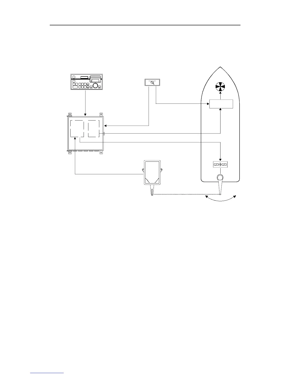
Fig. 1-10
Special applications, Example 1
In this example the autopilot is interfaced both to a conventional
rudder system, using ON - OFF solenoid valves, and an azimuthing
bow thruster with ±10V as control signal.
The AP9 MK3 can provide different parameters for the thruster and
the rudder control respectively, and the combination is determined
under the INFO loop 2 (Ref. page 2-9).
The combination shown above requires a Thruster Interface PCB to
provide the single ±10V analogue output, and a Thruster Selector
Switch to provide the change-over (C/O) signal to the thruster
combined with the mode control to the autopilot. The Thruster
Interface PCB, part no. 20126017 is mounted in the Distribution Unit,
and the solid state PCB must be specified according to the switching
voltage. (Ref. Standard System).