Robertson AP9 MK3 Autopilot
3-6 20169223D
3.5 RF14XU Rudder Feedback Unit
(For details, ref. installation)
The RF14XU Rudder Feedback Unit consists of a glass-reinforced fire
inhibiting polyester housing with a mounting plate of seawater
resistant aluminium. Potentiometer, limit switches and an electronic
drive module are also contained in the unit. The electronic drive
module comprises a voltage section and a frequency section.
The voltage section
outputs a voltage to the
rudder angle indicator(s)
which is proportional to
the rudder angle. The
voltage varies ±9V with
half of the supply voltage
as reference. The voltage
shall therefore read
“24VDC” supply/2 for
midship position.
The frequency section
outputs a signal to the
control unit with 3400 Hz
as midposition reference.
It varies at a rate of 20
Hz/degree, increasing
when the rudder moves to
port and vice versa.
The shaft of the Feedback
Unit is free to travel 360
degrees, but only ±90
degrees from midposition
are used for signal control.
RF14XU is equipped with two sets of limit switches. One set can be
connected in series with the autopilot solid state switch, the other can
be incorporated in an independent hand steering system, if required.
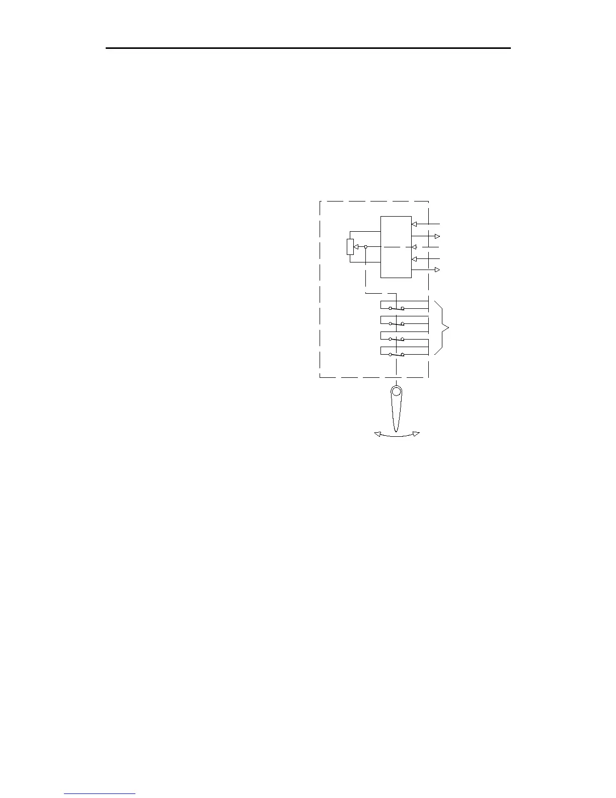
15V Supply from autopilot
3400 Hz +/-20 Hz/degree
Indicator supply
0 - 18V
Galvanic isolation
X/U CONVERTER
X
U
Limit switches
RF14XU
Feedback
pot.
1:1
RUDDER
Fig. 3-6
RF14XU principle