Robertson AP9 Mk3 Autopilot
5-30 20169223D
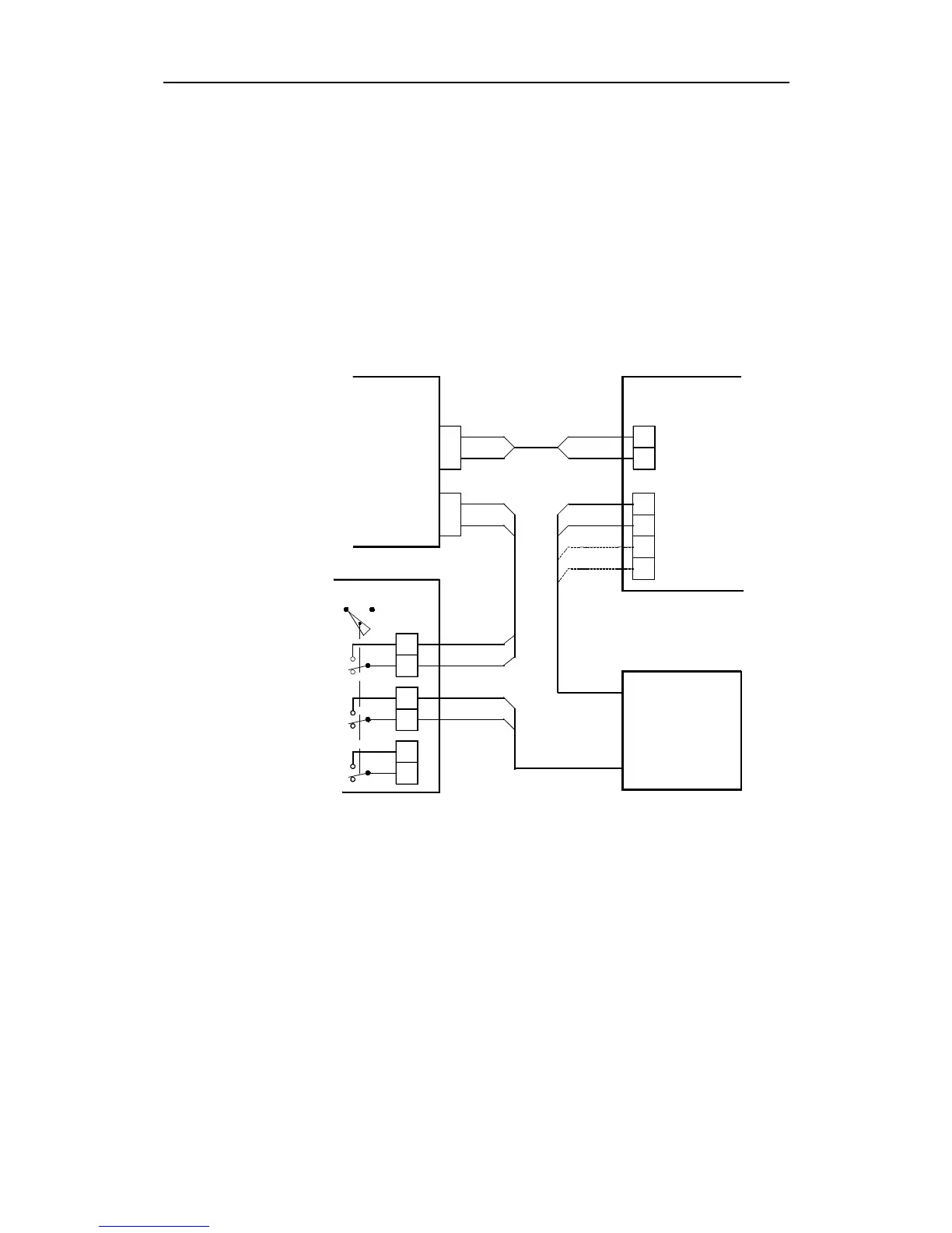
To enable the thruster interface, the standard Interconnection Board
(part no. 20125027) is replaced by the Thruster Interface Board (part
no. 20125017). This board will provide either one ±10V analogue
signal or one 4-20 mA current signal, generated from the control unit
via the Thruster Interface Board.
Note ! There are two versions of the Thruster Interface Board. The latest includes a
trim potentiometer (RV15) for adjustment of the output voltage level and is
marked with revision "A".
To enable the analogue signal from the control unit, a separate switch
must be used to ground the "thruster ON/OFF line" (J/P4). Refer to
Fig. 5-37.
1
2
3
4
31
42
11
13
J/P4
J/P2
1
2
3
4
ANALOG I/P
ANALOG I/P GND.
VOLT O/P
CURRENT O/P
CURRENT O/P
VOLT O/P
TB4
TB9
D9X
THRUSTER INTERFACE PCB.
AP9 MK3
MAIN CONTROL
UNIT
THRUSTER ON/OFF
THRUSTER
SIGNAL
THRUSTER SWITCH
C/O
THRUSTERRUDDER
1
2
3
4
5
6
Optional
"Standard"
version
Fig. 5-37
AP9MK3 /Thruster Interconnection
Whenever entering the "Thruster" function, separate settings of the
following parameters can be set:
• OFF COURSE LIMIT
• COUNTER RUDDER
• RUDDER
• WEATHER
When “Thruster function” is selected separate settings of THRUSTER
DEADBAND and MIN. THRUST are enabled. This means that
deadband for the analogue thruster signal can be set independent
from the ordinary Rudder Deadband. Also the gain (MIN. THRUST)
of the analogue signal can be set independent from the RUDDER