Design and theory of operation
20169223D 3-15
3.7 F200-40 Remote Control
This unit enable remote control of the AP9 MK3 Control unit.
A simplified diagram is shown below:
DISPLAY
IC3
LCD1
CLOCK
DATA
V
R
PORT
STBD
IC2-E
IC2-F
D1
D2
PORT
MODE
STBD
V
DC
P
M
S
PUSH
BUTTONS
H
L
H
L
D5 D6
V
DC
REG.
IC6
D9
R18D3
L3
+
_
SUPPLY
L4
COURSE 2
COURSE 1
IC5-A
IC5-B
OPTO COUPLERS
SPLIT ROTOR
COURSE KNOB
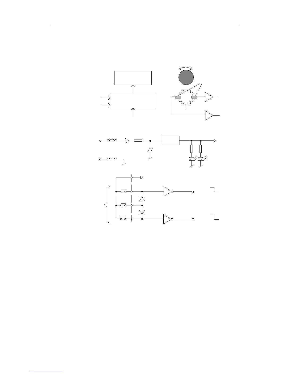
Fig. 3-15
F200-40 Simplified diagram
The F200-40 display is operated via clock and data signals from the
control unit and will display actual course or set course, dependent
of operational mode.
When turning the course knob, IC5-A and B will shape the pulses
generated by the two opto-couplers that are switched ON/OFF via
the split-rotor, and thus provide pulses as course 1 and course 2.
The operational mode of the control unit can be selected by the push
button M (Mode). This button provides both PORT and STBD signals
simultaneously by the two diodes D1 and D2. The sequence of mode
change is described under the OPERATION section.
When pushing the P and S buttons, the PORT and STBD signals will
switch to low (GND) and provide course change or NFU-steering
depending on the operational mode.