Robertson AP9 MK3 Autopilot
3-10 20169223D
Provisions have been made for offset and level adjustments of the
output signals by the SW1, containing four switches, and trim
potentiometers RV13-14 and 15. The adjustment procedure is
described under section Installation: Analogue signal, Rudder &
Thruster (page 5-50.).
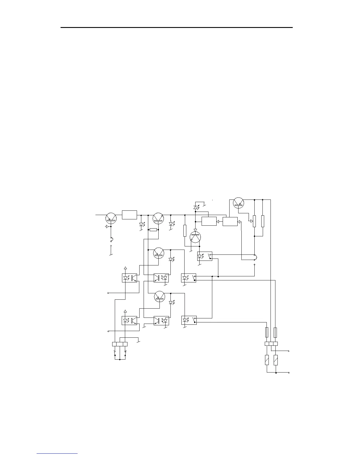
SOLID STATE BOARD
This PCB performs the switching of the solenoids.
There are three versions:
• D90: switching 19-40V DC, 3A
• D91: switching 110V DC, 1A
• D92: switching 110/220V AC, 1A
All versions are made from the same PCB. Only the components
related to the solid state switch-"relays" are different. The differences
are listed on the detailed schematics. (Drw. N1-012815)
A simplified diagram is shown below.
+15V
IC1
Q1 Q3
Q6
Q4
Q2
Q5
OPTO OPTO
REG.
IC3
LD4
IC2
IC5
IC4-B
IC4-A
LD3
PORT
STBD
IC6-C IC6-DLD2
LD1
LD5
4
5
6TB14
F1F2
13/4 2
SAFE
RELAY
V
R
V
R
R21
H
L
LIMIT SWITCH
TB12
SOL.
SUPPLY
V
R
S1
S2
S3
JUMPER
SWITCH
Fig. 3-11
Solid state PCB - Simplified diagram