Home
Simrad
Boating Equipment
Robertson AP9 Mk3
Simrad Robertson AP9 Mk3 User Manual
5
of 1
of 1 rating
202 pages
Give review
Manual
Specs
To Next Page
To Next Page
To Previous Page
To Previous Page
Loading...
Spare parts
20169223D
7-5
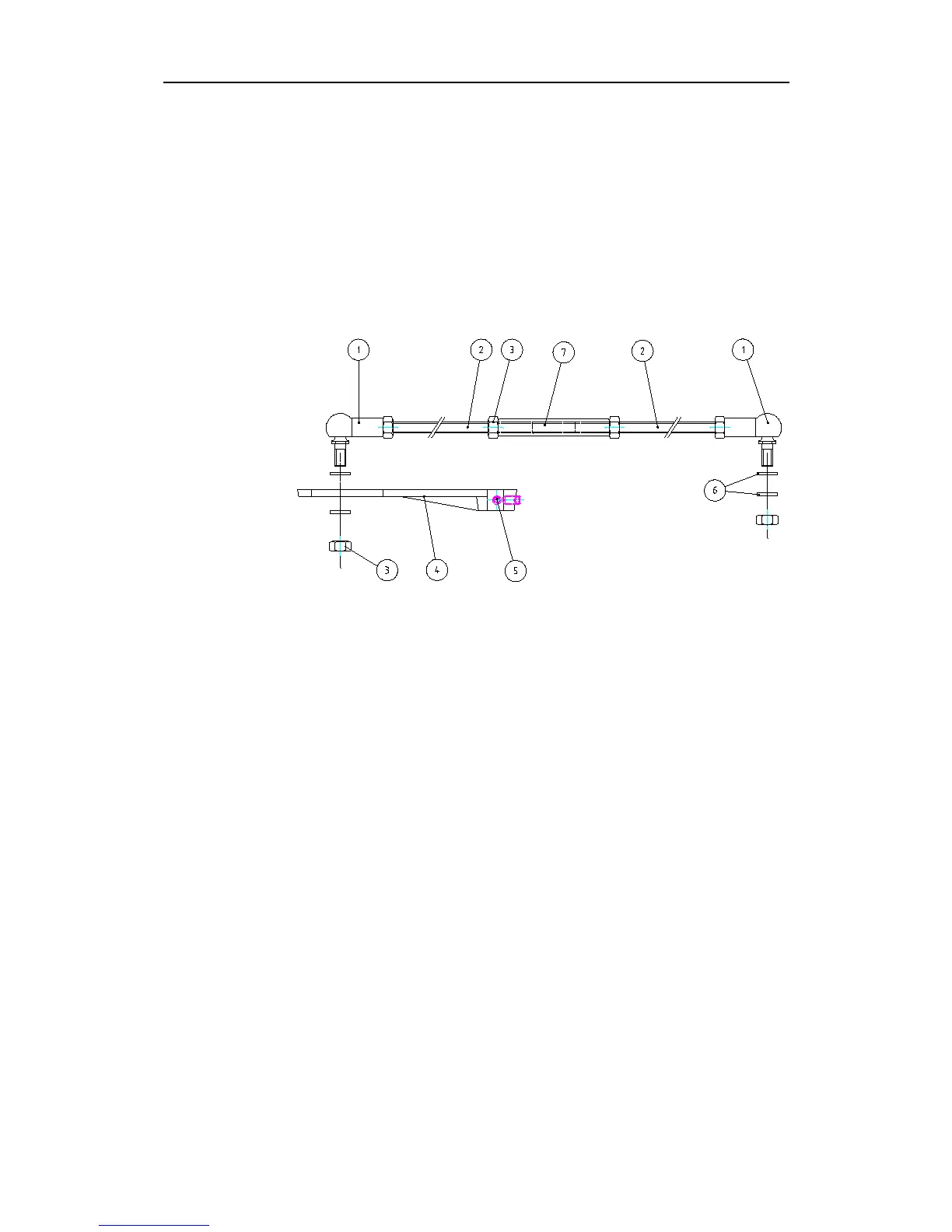
7.5
RF Standard Transmission link
22504005
Transmission link complete
44132306
1
Ball joint, 8 mm stainless
44132322
2
Transmission rod M8x300 mm
44150225
3
Lock nut M8 (Hex)
22504021
4
Transmission lever Ø12 mm
44152676
5
Socket set screw M6x10
44151967
6
Washer M8
22504054
7
Joint nut M8 (Hex)
Fig. 7-4
RF Standard Transmission link
172
174
Table of Contents
Default Chapter
5
Table of Contents
5
1 Introduction
13
General
13
MK3 System Layout
13
Options Available with the Standard System
13
Fig. 1-1 AP9 MK3 System Layout
14
AP9 MK3 Standard System, On-Off Valves
15
AP9 MK3 Standard System, Dual Analogue Output
16
AP9 MK3 with Analogue Thruster Control
17
Fig. 1-4 Thruster Control
17
Combinations of Heading Sensors
18
Gyro Compass
18
Fluxgate Compass
20
Dual Station
21
Serial Lines
21
Fig. 1-6 Serial Line Connections
21
Fig. 1-7 Dual Station System
22
Connection of Steering Levers
23
Fig. 1-8 NFU/FU Levers
23
Rudder Angle Indicators
24
Special Applications
25
Example
26
Example
27
2 Operation
29
General
29
Front Panel
29
Fig. 2-1 AP9 MK3 Front Panel
29
Mode Selection
30
HELMSMAN (Power ON)
30
Autopilot
30
Nav. Mode
30
Off
30
Alarm
31
Thruster/Rudder Parameters
31
Parameter Setting
31
General
31
Switch on
32
Helmsman
33
Autopilot
33
INCREASE- and DECREASE-Buttons
33
Illum
33
Compass Select
34
Rudder
34
Weather
35
Fig. 2-2 Rudder Settings
35
Counter Rudder
36
Info
37
Course Selection
43
Navigational Steering
43
General
43
Steering by XTE to Waypoint
44
Priority Mode (APB Sentence)
46
Ecdis Mode ( APB Sentence)
47
Remote Control
47
AP9 MK3 Dual Station
48
F200-40 Remote Control
49
S9 Steering Lever (NFU)
50
FOLLOW-UP Steering Levers
51
Fault Warnings
53
Heading Sensor Warnings
53
Other Fault Warnings
56
3 Design and Theory of Operation
59
General System Description
59
Fig. 3-1 Autopilot Principle Diagram
59
Fig
59
AP9 MK3 Control Unit
60
Fig. 3-2 Processor Controlled Autopilot
60
Fig. 3-3 AP9 MK3 Electronic Boards
61
Fig
61
CD109 Course Detector
62
CD109 Course Detector Principle
62
Course Handling
62
Fig. 3-4 Course Detector Principle
62
Fig
62
Fig. 3-5 AP9 MK3 Course Handling
63
RF14XU Rudder Feedback Unit
64
Fig. 3-6 RF14XU Principle
64
D90 Series Distribution Unit
65
Fig. 3-7 D9X Pcbs
65
Power Supply Board
65
Fig. 3-8 Power Supply PCB - Simplified Diagram
66
Fig. 3-9 Interconnection PCB - Simplified Diagram
66
Interconnection Board
66
Fig. 3-10 Thruster Interface PCB - Simplified Diagram
67
Thruster Interface Board
67
Fig. 3-11 Solid State PCB - Simplified Diagram
68
Solid State Board
68
Fig. 3-12 Solid State PCB - Connection of Limit Switches
70
Fig. 3-13 Solid State PCB - Connection of Solenoids
70
Dual Analogue Pcb
71
Fig. 3-14 Dual Analogue PCB - Simplified Diagram
72
F200-40 Remote Control
73
Fig. 3-15 F200-40 Simplified Diagram
73
FU91/92 Follow-Up Lever
74
Fu91/92 Simplified Diagram
74
4 Technical Specifications
77
AP9 MK3 Control Unit
77
AP9 MK3 Gyro Interface Board
78
CD109 Course Detector
78
RFC35R Rate Compass
79
Rfc35R Rate
79
RFC35NS Fluxgate Compass
80
RFC35N NMEA Compass
80
Distribution Unit
81
Fig . 4-4 D9X D
82
Fig
82
RF14XU Rudder Feedback Unit
83
RF Standard Transmission Link
84
S9 Steering Lever
84
FU91 Steering Lever
85
Fig . 4-8 Fu91 S
85
S35 Steering Lever
86
Fig . 4-9 S35 S
86
F1/2 Remote Control
87
F200-40 Remote Control
87
Fig . 4-10 F1/2 R
87
Fig
87
F200-40 Remote Controld
87
RI9 Rudder Angle Indicator
88
Fig
88
IP Protection
89
Specification of Messages
90
Bearing Steering
90
CTS Steering
90
Priority (Mixed) Steering
90
Speed Correction Signal (VTG)
90
5 Installation
91
Unpacking and Handling
91
General
91
Control Unit
91
Fig
91
Connector Assembly
92
Fig
92
Fig Fig
92
Ontrol Unit - Bracket Mounting
92
Screen Termination
93
Ontrol Unit - Connector Mounting
93
Heading Sensors
94
General
94
Magnetic Compass
94
Cd109 Course Detector Mounting
96
Gyro Compass
97
Rgc12 Serial Line Connection
99
RFC35NS Fluxgate Compass
100
Fig . 5-13 Rfc35
101
Ap9 Mk3 Control
101
Fig . 7-1 Ap9 M
101
RFC35N NMEA Compass
102
D90/D91/D92/D93/D99 Distribution Unit
102
Mounting
102
Rfc35N Nmea Compass Wiring to
102
Mounting
103
Electrical Connections
103
Fig . 5-16 B
104
Adjustments
105
RF14XU Rudder Feedback Unit
105
Mechanical Mounting
105
Ap9 Mk3 / D93
105
Electrical Installation
106
Fig
106
Rf14Xu - Mounting
106
Scaling of Rudder Angle
107
Fig . 5-19 S
107
Fig
108
Rf14Xu Internal Wiring
108
Final Check
109
Optional Equipment
109
AP9 MK3 Dual Station
109
Mode Selection (External Mode Selector)
111
Fig . 5-22 M
111
Fig
111
F200-40 and Mode Selection
112
Complete Mode Selections
112
Fig . 5-24 C
112
F200-40 as Mode Selector
112
Omplete Mode Selection
112
F200-40 Remote Control
113
S9 Steering Lever
113
Mounting
113
Fig . 5-25 F200 R
113
Fig . 5-26 S9 S
113
Electrical Connection
114
Function
114
Fig . 4-7 S9 S
114
Fig . 5-27 S9 S
114
Fig . 5-28 S9 S
114
Connection to
114
FU9X Follow up Steering Lever
116
Fig
116
Fig . 5-31 Fu9X S
116
Fig . 5-32 Fu9X
116
Fig . 5-33 S35
117
Fig . 5-34 S35
117
S35 Connection to D9X
117
Fig . 5-35 Ri9
118
RI9 Rudder Angle Indicator
118
Fig . 5-36 P
119
Fig
119
Analogue ±10V or 4-20Ma Control Signals
119
Fig
120
Fig . 5-38 N
121
Connection to Navigational Receiver
121
Start-Up and Commissioning
122
Selection of Parameter Settings
123
Fig . 5-39 I
124
Fig . 5-40 I
129
Fig . 5-41 "H
134
Dockside Alignment/Test
139
Rudder Angle Indicators
140
Fig . 5-10 S
141
Fig . 5-11 S
141
Deflection Test (Rudder or Azimuth Thruster Propulsion)
142
Fig . 5-43 D9X D
143
Fig . 5-44 D9X D
144
Fig . 5-45 D9X S
145
Fig . 5-46 D9X T
146
Tunnel Thruster Function
147
Fig . 5-47 G
148
Gyro Compass Selection
148
Magnetic Compass (CD109) Adjustments
150
FOLLOW-UP Levers
151
Sea Trial
152
RFC35NS Fluxgate Compass Calibration and Alignment
154
RFC35N NMEA and RFC35R Compass Calibration and Alignment
155
Fig . 5-48 R
156
On Course Steering
156
Course Changes
157
Save Parameters
159
Navigational Steering Test
161
Fig . 5-49 S
162
6 Trouble Shooting
163
CD109 Course Detector
166
Cd109 Course
166
Thruster Interface Pcb
167
Malfunction of the D93/D94
167
7 Spare Parts
169
AP9 MK3 Control Unit
170
Cd109 - Spare Parts
171
Rf14Xu - Spare Parts
172
RF Standard Transmission Link
173
F200-40 Component Reference
174
F200-40 Remote Control
174
FU91 Steering Lever
175
S35 NFU Steering Lever
175
S9 Steering Lever
175
Fig . 8-1 J1 - I
177
Fig . 8-2 J2 - I
177
Fig . 8-3 J3 - I
177
Fig . 8-4 J4 - I
177
Fig . 8-5 J5 - I
177
Fig . 8-7 D9X/S S
177
Fig . 8-9 D9X P
177
Fig . 8-10 D9X I
177
Fig . 8-11 D9X S
177
Creen Termination
177
8 Drawings
179
Fu9X - Circuit Diagram
185
Fig . 8-12 D9X D
189
9 Index
193
10 Appendix
195
Sales and Service Worldwide
201
Fig . 5-21 D
201
Fig . 5-29 P
202
5
Based on 1 rating
Ask a question
Give review
Questions and Answers:
Need help?
Do you have a question about the Simrad Robertson AP9 Mk3 and is the answer not in the manual?
Ask a question
Simrad Robertson AP9 Mk3 Specifications
General
Brand
Simrad
Model
Robertson AP9 Mk3
Category
Boating Equipment
Language
English
Related product manuals
Simrad NSO
116 pages
Simrad TP20
28 pages
Simrad TP30
28 pages