Introduction
20169223D 1-15
Example 3:
NOTE:
THE D94 CONTAINS ONE THRUSTER INTERFACE
BOARD AND ONE DUAL ANALOG PCB.
AP9MKII AUTOPILOT
AP9 MK3
THRUSTER SELECTOR
(SPECIAL)
D94
DISTRIBUTION
UNIT
DUAL
ANALOG
PCB
THR.
INT.
PCB
BOW
THRUSTER
AFT THRUSTERS
+/-10V
+/-10V
C/O SIGNAL
C/O SIGNAL
+/-10V
MODE
P
S
C/O SIGNAL
THRUSTER
ELECTRONICS
THRUSTER
ELECTRONICS
THRUSTER
ELECTRONICS
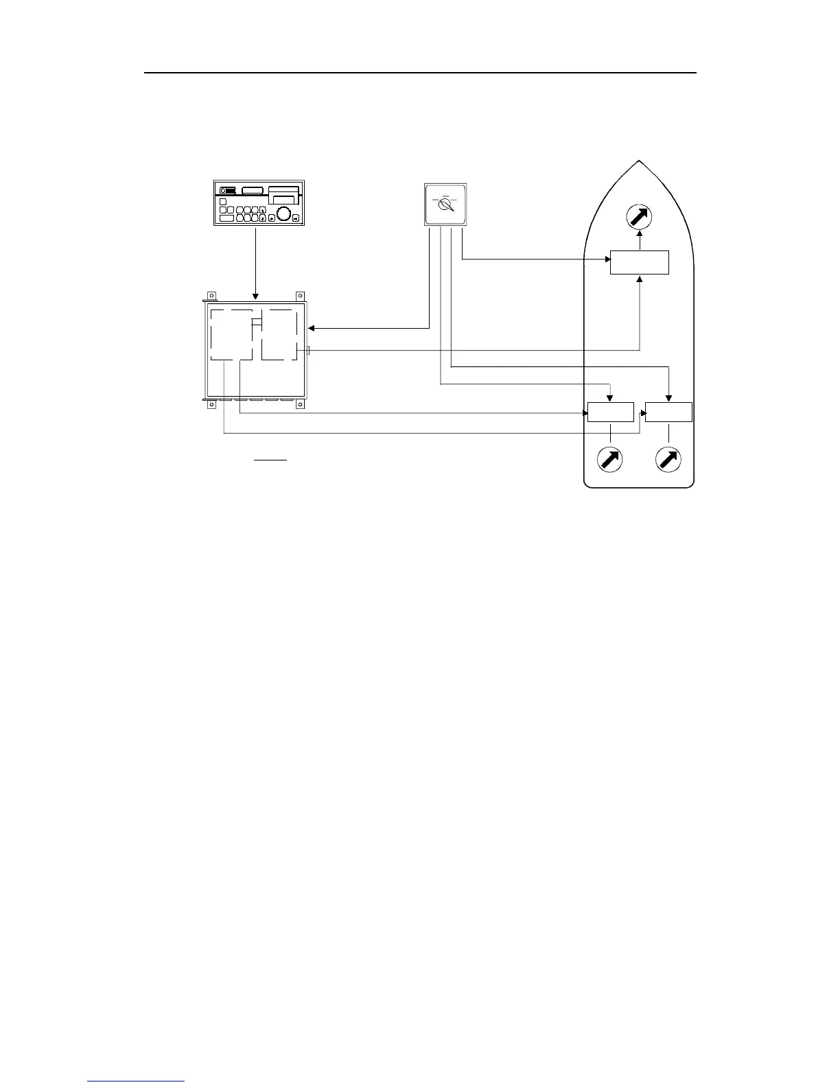
Fig. 1-12
Special application, Example 3
The AP9 MK3 autopilot system can provide three galvanic isolated
±10V outputs and be configured as shown in Fig. 1-12.
In this example the Distribution Unit is equipped with one Thruster
Interface board to control the bow thruster, and one Dual Analogue
PCB to control the two aft thrusters.
The Thruster Selector Switch is normally custom-made for each
individual system, and provides the change-over signals for the
thrusters, and the mode for the autopilot.
No Feedback Unit is required!
Thruster Selector Positions:
• MANUAL
• AUTO AFT (Aft Thruster)
• AUTO BOW (Bow Thruster)
FEATURES: First parameter set for synchronized operation of the
aft thrusters.
Second parameter set for the operation of the bow
thruster.