Installation
20169223D 5-49
5.19 Dockside Alignment/test
General
Prior to sea-trial, the system shall be "Dock-tested" for alignment and
pre-setting of parameters.
It is recommended that the following general procedure be followed.
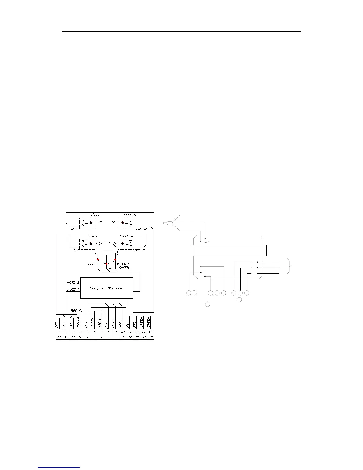
RF14XU Feedback unit (ON-OFF valves)
Make sure that the RF14XU Feedback unit is configured for the
correct rudder deflection direction and ratio (±45° - 60° - 70°- 90°).
The RF14XU is normally delivered for ±45° rudder angle (the yellow
and the green leads are soldered together). Violet, brown and pink
leads are not connected. For ±60° rudder angle, connect yellow and
brown leads. For ±70°, connect yellow and violet leads, and for ±90°,
connect yellow and pink leads. Also ref. to the fig. below.
For change of deflection, make the connections in accordance to the
following list.
Note ! Make sure that J1-5 (FB LO) is terminated at a GND point such as TB3-5.
To check the autopilot for connected rudder response, make the
following test:
•
Set Counter Rudder to OFF
•
Set Rudder to 1
•
Set Weather to OFF
VIOLET
BROWN
PINK
BLACK
RED
WHITE
WHITE
BLACK
RED
BLUE (GND)
YELLOW (+5V)
GREEN (WIPER)
NOTE 1
NOTE 2
9810
7
6
5
RF14XU ELECTRONIC MODULE
(VIEWED FROM BACK SIDE)
NOTE 1: Brown lead normally connected to .
Move to to invert the rudder indicator deflection.
NOTE 2: Normally connected for +/-45˚ rudder angle (violet, brown and pink leads are
not connected). For +/-60˚ connect brown lead to terminal 10, for +/-70˚ connect
pink lead to terminal 10, for +/-90˚ connect violet lead to terminal 10.
White lead must remain connected.
BROWN
8
9
8
9
TO
POT.
METER
Fig. 5-42
RF14XU Internal Wiring