Robertson AP9 Mk3 Autopilot
5-6 20169223D
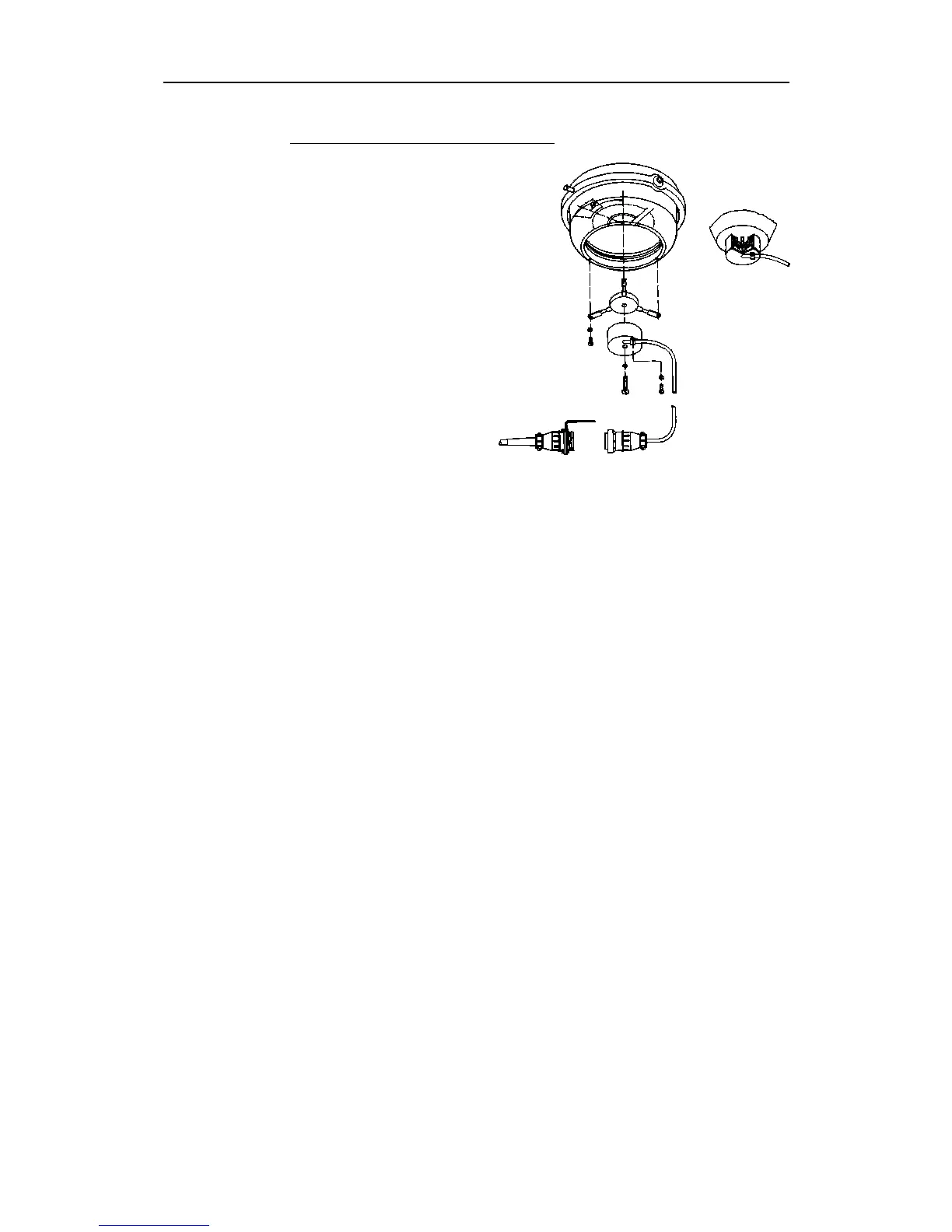
CD109 Course Detector mounting
The course detector is
mounted on the ship's
magnetic compass to
transmit the compass
signal to the control unit.
The mounting method will
depend upon the compass
design. The distance
between the course
detector and the compass
card depends upon the
magnetic momentum of
the compass card magnets.
A distance of 70-90 mm for
a magnetic momentum of
1500-2000 cgs is therefore
recommended. For adjust-
ment of signal level, see
below.
For mounting instructions refer to Fig. 5-6. The course detector can be
attached to the compass either by a 6 mm screw to the bottom of the
compass bowl or by use of the tri-pod holder supplied with the
course detector.
The course detector is also supplied with cable (1m) and plug. Socket
and connector with bracket for extension cable are in the standard
scope of supply. The extension cable is optional equipment.
The compass should be checked for free movement in the gimbals
without stressing the detector cable.
The CD109 Course Detector is connected to J2 or J3 of the control
unit, and the connection is shown on the External Wiring Diagram.
When connecting two magnetic compasses, one must be connected to
J2 and the other to J3.
If the Course Detector is mounted on the top of the compass, the
sine/cosine signal on J2/J3 pin 10 and 11 must be interchanged.
Adjustment of signal level
The control unit supplies a 2.5V reference voltage (V/2) to the Course
Detector secondary windings, together with exciter pulses of fixed
frequency to the primary winding.
The resultant voltage on the secondary windings follows the sine and
cosine of the compass heading. The peak values of the sine and
cosine signals are dependent on the distance between the course
detector and the compass magnets. Both the reference voltage (V/2)
called CENT.SIN1 and CENT.COS1 and the sine and cosine voltages
called COMP1 SIN and COMP1 COS (0-5V approximately) are
Fig. 5-6
CD109 Course Detector mounting