Robertson AP9 Mk3 Autopilot
5-58 20169223D
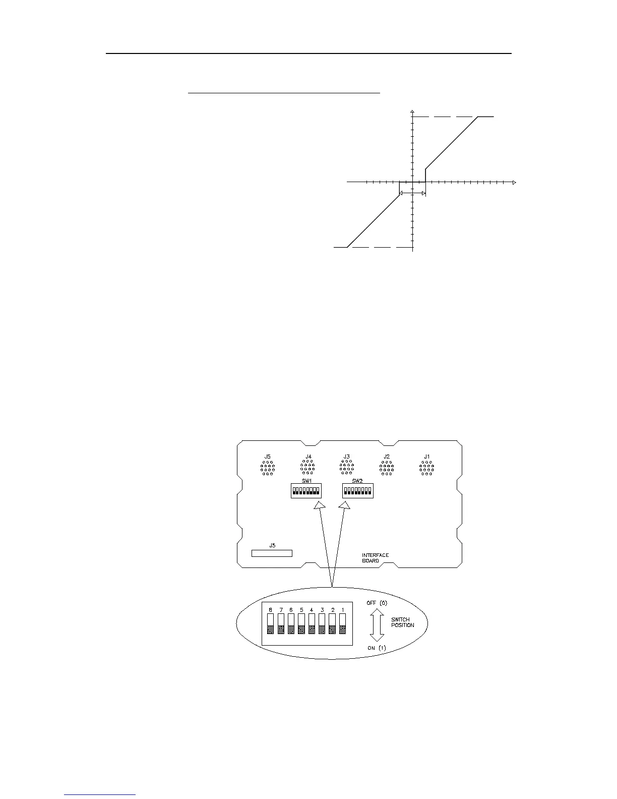
Minimum Thrust & Thruster deadband
This example shows how the
control signal will appear for
a combination of deadband
and minimum thrust.
The control signal will stay at
zero until the heading error
exceeds 2 degrees. Than a
25% power signal will be
applied.
The final values of the
different parameters are
selected during sea trial.
Gyro Compass selection
The AP9 MK3 Control Unit must be set up for the correct type of
gyro. This means that selection of 1:1 synchro either from the gyro or
the autopilot and current phase and reference voltage.
This is done by means of two packages of DIP switches, 8 switches
each, located on the back of the Interface board (See Fig. 5-47.)
Note ! All switches are factory set to OFF-position. Carefully check whether an
eventual 1:1 synchro is excited from the gyro or not. SW1-7/8 must NOT be
ON if the gyro provides excitation, or damage of the gyro interface module
will occur.
Fig. 5-47
Gyro Interface board, switches
If the synchro is "DEAD", switch on SW1-7/8. Appr. 15V, 400Hz
signal square wave signal will excite R1-R2 of the synchro.
U
+10V
(100%)
Deadband ±2°
-10V
Heading error
20%
Min. Thrust 20%