Installation
20169223D 5-21
5.8 Mode selection (External mode selector)
(For connection diagram of optional equipment, refer to section 8.)
The mode selector lines from the AP9 MK3 Control Unit J1 are
marked as:
A: Modus 1 NFU (J1-1)
B: Modus 2 FU (J1-2)
Whenever one of the mode lines is connected to common (J1-13), the
selected mode will be entered. The mode will however change to
NFU when the mode line is disconnected from common.
It is also possible to arrange the mode lines for absolute control of the
modes.
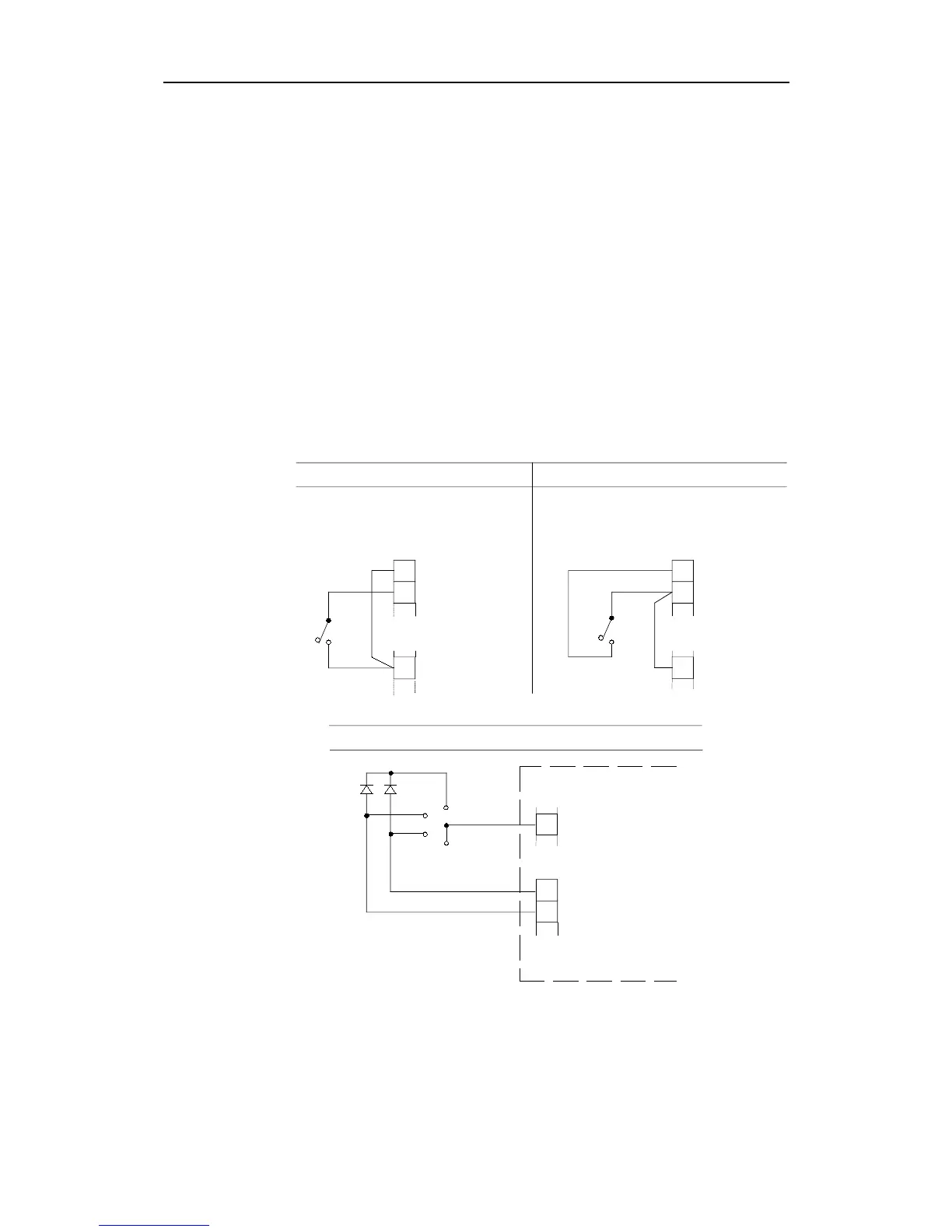
By one single ON-OFF switch, the autopilot can be connected to alter
between NFU-AUTO or FU-AUTO as follows:
1
2
MODE 1 NFU
MODE 2 FU
TB1
D9X INTERCONNECTION PCB
AUTONFU
MODE SELECTOR
Link
NFU - AUTO FU - AUTO
1
2
MODE 1 NFU
MODE 2 FU
TB1
D9X INTERCONNECTION PCB
AUTOFU
MODE SELECTOR
Link
5
TB3
COMMON
5
TB3
COMMON
5
TB3
COMMON
1
2
MODE 1 NFU
MODE 2 FU
TB1
OFF
AUTO
NFU
FU
D9X INTERCONN. PCB
D1
D2
D1=D2=IN4006 or similar
OFF - NFU - FU - AUTO
Fig. 5-22
Mode Selector connection
Caution ! F200-40 can be used only when the mode selector includes
an OFF position to disable external mode selection.