Robertson AP9 Mk3 Autopilot
5-2 20169223D
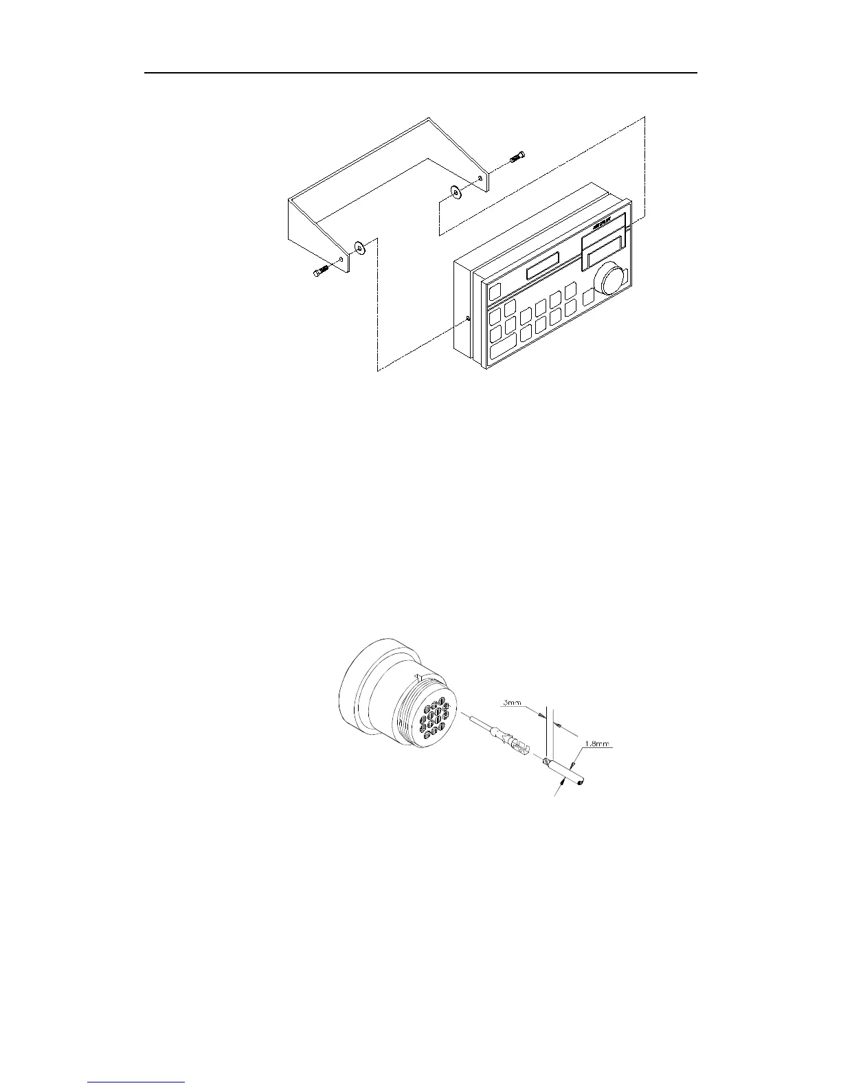
Fig. 5-2
Control unit - bracket mounting
Connector assembly
The cable conductors are connected to the connector block according
to the connection lists drw. no. N4-016896. The following tools are
required to crimp the connector pins and sockets to the individual
cable conductors:
Crimping tool : Amp 58495-1
Extraction tool: Amp 725840
Note ! Do not use other tools than those specified!
Fig. 5-3
Connector assemble
For protection against electro magnetic interference, all control unit
connectors must be fitted with the supplied metal shell and cover. In
addition, the cable for J1, J2 and J3 must be fitted with the supplied
ferrite cores.