Robertson AP9 MK3 Autopilot
3-8 20169223D
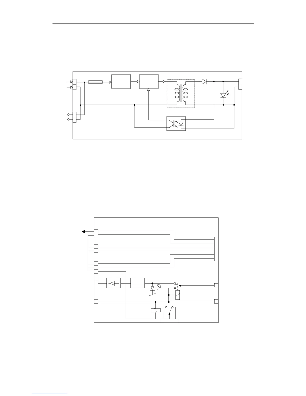
DC voltage is coupled via the isolation transformer T1 to the rectifier
diode D2. The filtered 15V DC voltage is regulated by the feedback
line through the optocoupler to maintain isolation.
The green LD1 indicates presents of voltage.
24V DC
+
_
24V DC
TO EXTRA
SUPPLY
1
2
1
2
+
_
FILTER
OSC.
TB1
TB2
TB3
OPTO COUPLER
FEEDBACK
T1
D2
15V
LD1
FUSE
2.5A
Fig. 3-8
Power supply PCB - Simplified diagram
INTERCONNECTION BOARD
(For detailed diagram, refer to SCHEMATICS)
The AP9 MK3 Control Unit is connected to the distribution unit via
one cable from J1, terminated to TB1, TB2 and TB3.
The Interconnection Board provides distribution of the signals to the
BUS plug.
TB1
TB2
TB3
BUS
PLUG
AP9 MK3
CONTROL
UNIT J1
DB1
REG.
24V DC
LARM
VOLTAGE
15V DC
REG. FROM
P.S.B.
15V ALARM TO
AUTOPILOT
15V MAINS TO
AUTOPILOT
K1
K2
ALARM
LD1
Fig. 3-9
Interconnection PCB - Simplified diagram
The 24V DC alarm voltage is connected to TB3. Polarity of voltage is
not critical as the bridge rectifier DB1 rectifies the voltage. The 24V